• Steel Soldiers now has a few new forums, read more about it at: New Munitions Forums!

  • Microsoft MSN, Live, Hotmail, Outlook email users may not be receiving emails. We are working to resolve this issue. Please add support@steelsoldiers.com to your trusted contacts.

M1009 wiring questions

placek59

New member
12
12
3
Location
SE Nebraska
Hello All,

I got an '84 M1009 a few months ago and have been tinkering on it and trying to make it more reliable. It had a fuel leak from the lift pump to the fuel filter. I cut that hard line and used fuel hose to replace the section the 16" ~ish section from where the line was leaking to the fuel filter. After doing that, I have been having intermediate glow plug issues.

Sometimes I get no wait light at all, most of the time it would stay on forever (I turned the key off after 30 seconds or so), and once it worked as it should have so we got to go for a drive last Saturday and fueled up! Might have put 15 miles on it cruising around the countryside.

My questions are:
1. How do I remove the glow plug card under the dash? I removed the black cover and tried to pull it out gently, but didn't want to force it and possibly break some brittle old circuit board. They should just pull straight out, correct? I wanted to clean the contacts and inspect the board.
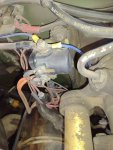
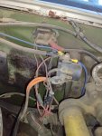
2. I suspect the relay on the firewall is shot as I was not getting any voltage out of the bottom post while the key is turned on and have no continuity between any of the terminals or posts. I have 12v to the top large post and get 12v to the upper small post. I bought a new relay but haven't installed it yet. There is a mystery blue wire going from the resistor bank to the top post and then from the top post into the fuse box under the dash. It is just plugged into a fuse location. Any idea what the thought behind that may be? See the pictures for a better idea.
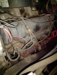
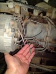
3. I found a green wire not connected to anything hanging by the driver's side alternator. Any idea where it might go? I don't see anything obvious. It looks like a glow plug wire but all 4 plugs have wires on them. I did not check it for voltage or any continuity to ground or anything else. I didn't see any green wire on the charging system diagram. Again, see pictures.

I hope to get out to work on it some this weekend and do some more cleaning of grounds and chase some gremlins. I have the glow plug wiring schematic printed out to use too.
Thanks,
KP
Blazer wire1.jpgBlazer wire2.jpgBlazer engine bay.jpgGlow plug relay.jpgBlazer glow plug relay.jpg
 

WWRD99

Well-known member
Steel Soldiers Supporter
1,117
1,715
113
Location
York Pa
Ok, I'll try and remember all the parts you got goin on! First that wire by the alternator goes to a sensor in the head that looks like it is plugged right now...very front side by the injector. I'll hunt that part number out. The wire running to the glow plug relay is interesting...comes from the positive block then to the top relay then to the fuse box. Odd. Unplug the wire in the fuse box and see what stops working. No idea whats goin on with that. I'd replace the relay and not install that wire and figure out the 2 control wires for the relay. The bottom little post would be a ground so you won't find power there. Ground comes from the card from the temp sensor on the rear drivers side head. To remove the card it does take some pull. It is heald in pretty tight. The gp relay doesn't look stock which isn't a big deal but might be the wrong one hence that wire popped on it. As far as the wait light staying on for a long time then sometimes it works right does point to the temp sensor in the rear of the drivers head. You should be able to hear the gp relay click from inside the cab.

Ok so I looked closer at the gp relay pic. They used that wire to feed the relay but it's not correct. It's supposed to be fed from the block above the relay to the top post. I'll try n take pic of one of mine.
Sent from my SM-S906U using Tapatalk
 

WWRD99

Well-known member
Steel Soldiers Supporter
1,117
1,715
113
Location
York Pa
Yes...I'm thinking that wire off the block should be 24 volts...which is wrong you need 12...the wire coming off the battery will give you 12 volts. You might have fried glow plugs with 24 volts going to them as well. Maybe that wire goes in yo the block to feed 24 volts to the relay it would be the most bottom fuse in the block if it is. Could have fried the relay too.


Sent from my SM-S906U using Tapatalk
 

Lothar

Well-known member
324
661
93
Location
North Arkansas
Great help there. I will add that extracting the card is made easier by pulling with a hook pick in the little hole on the end of the card. I grab one side with fingers and hook pick the other side. Just be sure to disconnect the batteries first.
 

WWRD99

Well-known member
Steel Soldiers Supporter
1,117
1,715
113
Location
York Pa
Great help there. I will add that extracting the card is made easier by pulling with a hook pick in the little hole on the end of the card. I grab one side with fingers and hook pick the other side. Just be sure to disconnect the batteries first.
I never noticed a hole in the card!! Great to know! That would make it very easy to remove. The one I just put in my sons 09 is very tight and wanted to try a different card but it fought me coming out.
 

WWRD99

Well-known member
Steel Soldiers Supporter
1,117
1,715
113
Location
York Pa
Once you get the card out, use a pencil eraser to clean the contacts on the printed circuit contacts. Just abrasive enough to clean without removing anything important.
I didn't think of using the eraser trick! I like that better as I use 1000 grit sandpaper but it's sketchy since I could mess the board up!
 

WWRD99

Well-known member
Steel Soldiers Supporter
1,117
1,715
113
Location
York Pa
Thanks guys! I just plugged in the block heater. If it quits raining/drizzling this afternoon I hope to be able to get some work done
Good luck with that rain!! I looked at your pics on my laptop and it looks like there is a wire coming from the battery to the block above the gp relay already. You can run a wire from it to the top of your gp relay. You can see that in my pic. I used the original fusible link wire off the original gp resistor to do that. I'm not sure if it has to be a fusible link since the wire going to that block should have one on it though. It needs to be a big wire though! There's a bunch of those resistors online that should have that wire if you want it spot on. I also see that the sensor that the wire hooks to in the head is there but I can't see if the end is broke off or not. It could be stuck in the connector. I found the one I bought several years ago on ebay so at least you have the part number. If it is broken it will leak coolant when you replace it. Just have the new one taped up and ready and pop it in fast! I replaced my glow plugs with 60g...the original plugs don't fit them so I had to change the ends to the size that comes in pretty much all connector kits. The passenger rear are a pain to get to but doable.


Sent from my SM-S906U using Tapatalk
 

placek59

New member
12
12
3
Location
SE Nebraska
Finally got a chance to work on the blazer today! Replaced the glow plug relay with one from Napa and it fired right up!!! I am only getting 12.3 on one battery so I'll need to check the alternator output. It's nice to be able to enjoy driving a bit now while chasing details again! Thanks for the help!
 

WWRD99

Well-known member
Steel Soldiers Supporter
1,117
1,715
113
Location
York Pa
Great news! You find you're getting 12 or 24 volts to that relay?

Sent from my SM-S906U using Tapatalk
 

WWRD99

Well-known member
Steel Soldiers Supporter
1,117
1,715
113
Location
York Pa
12.5ish V to the relay
Ok was curious with the wires going to the top of the relay one being blue and the other fat battery looking cable hooked to it. What are they hooked to or are you converted to 12 volt now.
 

emeralcove

Member
Steel Soldiers Supporter
134
15
18
Location
Battle Ground/WA
Hopefully some one can help me on this alternator problem. I recently had my "GEN 1" alternator "Fail". I first noticed the "GEN 1" light came on with the engine running, something it never did before. The "GEN 2" commonly will do this but goes out once the RPM is increased, the volt meter needle jumps to the green and the "GEN 2" goes out until the engine is restarted and has never been a problem. The "GEN 1" now comes one and stays on after the engine is running, increasing the RPM increases the brightness of the "GEN 1" until the lamp burns out at which time the alternator ceases to generate voltage. I assumed the alternator was bad and purchased a rebuilt one, installed it only to still have the same condition. I have owned this vehicle since September 2011 and have enjoyed nearly 100,000 miles of reliable service, and any repairs it needed I have been able to do myself. This one has me stumped (full disclosure, Electrical problems are not my strongest suite but the CUCV aren't too complicated and until now I've been able to squeak by) Any suggestions are greatly appreciated.
 

emeralcove

Member
Steel Soldiers Supporter
134
15
18
Location
Battle Ground/WA
Reading deeper in different posts I found a reference to another member being helped with troubleshooting a bad fusible link that caused an alternator to not charge. I noticed one of my fusible lings had been replaced previously and one of the butt connectors was dark under the insulation. I checked continuity and found it was "open". After repairing this previous "repair" ( probably done by me years ago when I first got the vehicle home from Nellis Air
Force Base and trying to get it running) the charging system is working again, although it runs at the line between green/red on the voltage gauge when engine is running at highway speed. The bonus is the wipers no longer drag across the windshield and the engine starts instantly. Hopefully my stumbling across the solution to my problem might help someone else. The old saying of "even a broken clock is right twice a day" is true but I'm sure Minilineals may not get the joke if they can't read an analog clock.
 
Top