• Steel Soldiers now has a few new forums, read more about it at: New Munitions Forums!

  • Microsoft MSN, Live, Hotmail, Outlook email users may not be receiving emails. We are working to resolve this issue. Please add support@steelsoldiers.com to your trusted contacts.

M1010 DUVAC Removal Plan "B"

jpg

Member
611
15
18
Location
Boston, MA
I should mention that I'm having my M1010 alternator work done by a professional mechanic who is very familiar with CUCVs and their electrical systems. I understand this stuff well enough to have a healthy respect for how much damage one can do if you wire up big batteries and alternators incorrectly.

If you're not familiar with DC circuitry, you don't want to learn on a CUCV. You want to learn using flashlight batteries, not truck batteries capable of doing serious damage to you and/or your truck.
 

Another Ahab

Well-known member
17,991
4,536
113
Location
Alexandria, VA
If you're not familiar with DC circuitry, you don't want to learn on a CUCV. You want to learn using flashlight batteries, not truck batteries capable of doing serious damage to you and/or your truck.
That sounds like very reasonable advice. I don't doubt that is true. Thanks for making the mention here.
 

TechnoWeenie

Well-known member
Steel Soldiers Supporter
1,653
1,669
113
Location
Nova Laboratories, WA
Keep in mind that the newer hawker batteries are AGM and as such have an extremely high absorption rate. Any AGM battery used as a deep cycle and charged by the alternator will tax the alternator as the battery will take up to Cx3 or Cx4... Meaning If you have a 100ah battery, the AGMs will absorb 300 (or 400) amps continuously in the bulk charge phase.

This is why you hear of people who hate AGMs because 'I bought one and it fried my alternator'.. Their alternator was already weak, and forcing an alternator to 100% output for an extended time... Ie to charge multiple 'house' batteries in an RV.... Can tax the system into failing.
 

jpg

Member
611
15
18
Location
Boston, MA
Right. I got lead/acid batteries. I wasn't sure I'd be able to get the M1010 charging system to correctly handle any other battery technology. I'm having enough trouble getting it to handle the lead/acid batteries for which it was designed.

There are alternators and voltage regulators out there that can be set to properly handle lead/acid and/or AGM and/or gel batteries. I suppose one could put such a charging system on an M1010. But to put those batteries into a system designed to charge lead/acid invites a whole new set of issues. I'm having enough issues as it is. :?

Keep in mind that the newer hawker batteries are AGM and as such have an extremely high absorption rate. Any AGM battery used as a deep cycle and charged by the alternator will tax the alternator as the battery will take up to Cx3 or Cx4... Meaning If you have a 100ah battery, the AGMs will absorb 300 (or 400) amps continuously in the bulk charge phase.

This is why you hear of people who hate AGMs because 'I bought one and it fried my alternator'.. Their alternator was already weak, and forcing an alternator to 100% output for an extended time... Ie to charge multiple 'house' batteries in an RV.... Can tax the system into failing.
 

Recovry4x4

LLM/Member 785
Super Moderator
Steel Soldiers Supporter
34,012
1,808
113
Location
GA Mountains
Mine is mentioned on here. Its the one with both alts replaced with 12V Leece Nevilles. It has worked flawlessly for years.
 

jpg

Member
611
15
18
Location
Boston, MA
I just purchased a M1010. Haven't seen her yet but when I do I suspect this will be one of my first Mods. "Plan B" seems the most logical.
I've run Plan B for 12K miles so far. If I had it to do over again, I'd go with 2 12V alternators. The 24V alternator rebuild kit is $650 just for the parts! It's also hard on belts. Some say the 12V and 24V voltage regulators will confuse each other in the Plan B configuration, and not charge the batteries optimally. I can't tell if that's happening sometimes on mine. If my 24V alternator dies, I'll replace it with a 12V, with the appropriate wiring changes, of course.

I use a battery tender, which indicates the state of the battery it's charging. Sometimes, when I come back from a drive & plug in the battery tender; it tells me that the battery isn't fully charged as it should be after a long drive. I've spent time poking around with meters to figure out exactly what's happening, without success. I don't know if the Plan B configuration is causing the voltage regulators to confuse each other sometimes, or maybe my battery tender is imperfect, or maybe something else is happening. I do know that 2 12V alternators would eliminate this mystery for me, since the voltage regulators would operate independently and as designed. The voltage regulator designers never imagined anyone would try the Plan B configuration. They're not exactly sure how that works. I know because I asked them.

This is all discussed in detail my thread, http://www.steelsoldiers.com/showthread.php?135493-M1010-for-my-daughter-the-field-biologist
 

jpg

Member
611
15
18
Location
Boston, MA
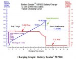
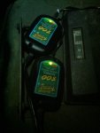
I have some new information on this. I bought 2 new Battery Tender 800s, one for each battery. They have 3 stages, bulk, absorbtion, and float. The charger's LED goes from red to flashing green to solid green as the battery is topped off. After driving my M1010, when I plug in the chargers, the front battery stays red substantially longer than the back battery. I've switched the 2 chargers between the 2 batteries, and the front battery consistently requires more charging to bring it to fully charged. This is true after a 2-mile errand or a 400-mile drive.

This gives me further cause to suspect that the voltage regulators are confusing each other, and that 2 12V alternators would be a better approach than 1 12V and 1 24V. It also argues for rotating the batteries.

I'm not sure the front battery is under-charged enough to make a difference in battery life. I don't have the means to measure or evaluate that. But there does seem to be a measurable difference.

bc.jpgimage.jpg

The chargers are not yet permanently mounted, but they do seem to work well.
 

Recovry4x4

LLM/Member 785
Super Moderator
Steel Soldiers Supporter
34,012
1,808
113
Location
GA Mountains
I wish I had the ability to capture similar data on mine since it has two 12V alts. I can say this, it works. I am considering using an ambulance setup along with the A/C stuff on another civy project. It is that dependable.
 

jamesgrizzlyadams

New member
8
0
1
Location
Ottawa, Ontario, Canada
I have an M1010 and completed the "Plan B" DUVAC removal a little over a year ago, it was working great until this weekend: now my 24V alternator has bit the dust. Rather than spend the money to rebuild the 30yr old 24V alternator, I'd like to replace it with an isolated ground 12V alternator that I can use to charge the rear battery. Revocry4x4, what alternator make/model do you have charging your rear battery? Is it the CUCV alternator or is it a newer one? If I need to I can order a CUCV alternator from somewhere like "rare electrical" online, but after the exchange rate and shipping up to Canada it's a pricey option. Are there any alternative alternators that people have used? Will any "true" isolated ground alternator with the right frame size etc work?
 

BushEngineer

New member
18
0
1
Location
Pell city, AL
Has anyone tried to turn both individual regulators to low, delete the DUVAC, and rewire top alt to the front battery?

http://www.thedieselpageforums.com/tdpforum/archive/index.php/t-6308.html


Sent from my XT1254 using Tapatalk
I have and was seeing 16.8+ volts. This was with the regulator set to low and sending 12V to the ignition terminal straight from the battery. I considered trying an 12V external regulator(which i still think is possible) to control only 12V like the original design achieved but decided to go Plan B instead. I bypassed all the Duvac/Regulator and went with the 12V Delco Remy 8600310(short hinge(stock is "Long Hinge") so required some additional mods to fit).
 

Mad Texan

Well-known member
Steel Soldiers Supporter
657
1,150
93
Location
Chester County, PA
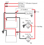
I did a diagram in paint for my own reference after reading over this several times and looking at pictures I could find. If I made a mistake please let me know so I can correct it but I think I got it.

I think it's time to Un-DUVAC... The m38inmaine/ChevyC60 Plan B

Added fuses in as a guide... when I get a better idea for the 12v feed fuse I'll add somethingm38inmaineChevyC60PlanB.png
 
Last edited:

richingalveston

Well-known member
1,715
120
63
Location
galveston/Texas
I think the wiring harness uses the 12 volt block for input to the second alt and the 12 volt alternator output goes to same block alto the battery goes to this block. just draw in the 12 volt block I believe would make it correct
 

joshuak

Active member
747
214
43
Location
Slower shore, DE
I may be mistaken, it certainly wouldn't be the first time, but AFAIK, m38inmaine's only replaced the top alt. with a 12v Leece Neville (110-555JHO) leaving the bottom alt. to satisfy the 24v needs and ChevyC60 replaced both alts with the 12v Leece Neville (110-555JHO).

So your diagram would be correct for ChevyC60's version, I'd like to suggest that you add a fuse to your positive connections.

No need for for an exciter circuit when using the Leece Neville (110-555JHO) they are self exciting. :jumpin:
 

Mad Texan

Well-known member
Steel Soldiers Supporter
657
1,150
93
Location
Chester County, PA
I may be mistaken, it certainly wouldn't be the first time, but AFAIK, m38inmaine's only replaced the top alt. with a 12v Leece Neville (110-555JHO) leaving the bottom alt. to satisfy the 24v needs and ChevyC60 replaced both alts with the 12v Leece Neville (110-555JHO).

So your diagram would be correct for ChevyC60's version, I'd like to suggest that you add a fuse to your positive connections.

No need for for an exciter circuit when using the Leece Neville (110-555JHO) they are self exciting. :jumpin:
I will reuse the original red wire from the lower alternator that has a fusible link at the bus bar. Looking at the wiring diagrams the yellow wire off the upper alternator goes to the DUVAC without a fusible link. If I add a fuse in, what are the thoughts on amperage to the battery? Old Alt was 100 amps and new Alt is 160 amps, but obviously at different voltages.

Looking at a Blue Sea fuse block which would add fuses for other connections that currently are not, the 12 volt block and glow plug relay.

https://www.bluesea.com/products/5196/MRBF_Surface_Mount_Fuse_Block_-_Common_Source

Edit: Looking at pictures I took of the truck my 12v and GP relay still have fusible links to them
 
Last edited:

Mad Texan

Well-known member
Steel Soldiers Supporter
657
1,150
93
Location
Chester County, PA
I think the wiring harness uses the 12 volt block for input to the second alt and the 12 volt alternator output goes to same block alto the battery goes to this block. just draw in the 12 volt block I believe would make it correct
The 12v block is fed off the positive for the front battery or the negative of the rear battery. I can add it in but I was mainly covering the installation of two 12v alternators in place of the two 24v ones. I will get it added for further clarification, I can also add a 12v feed for the GP relay if so bypassed.

And a Joshuak said the LN 110-555jho's are self exciting, getting rid of the exciter circuits
 

joshuak

Active member
747
214
43
Location
Slower shore, DE
I will reuse the original red wire from the lower alternator that has a fusible link at the bus bar. Looking at the wiring diagrams the yellow wire off the upper alternator goes to the DUVAC without a fusible link. If I add a fuse in, what are the thoughts on amperage to the battery? Old Alt was 100 amps and new Alt is 160 amps, but obviously at different voltages.

Looking at a Blue Sea fuse block which would add fuses for other connections that currently are not, the 12 volt block and glow plug relay.

https://www.bluesea.com/products/5196/MRBF_Surface_Mount_Fuse_Block_-_Common_Source

Edit: Looking at pictures I took of the truck my 12v and GP relay still have fusible links to them

I'm happy with the products I've purchased from Blue Sea, I used the fuse block linked bellow to replace the 12v block.

https://www.bluesea.com/products/7725/SafetyHub_100_Fuse_Block


About fuse size, I don't know enough to tell you what's best for that scenario. Hopefully a member in the know will chime in.


IMHO, the OEM gauge wire is not up to the task, the TM lists that yellow cable as an 8 awg, which used in a critical circuit, in an 8' long run is rated for 40-80 amps depending on application.

http://www.offroaders.com/technical/12-volt-wiring-tech-gauge-to-amps/

https://www.westmarine.com/WestAdvisor/Marine-Wire-Size-And-Ampacity

Blue Sea has a reference section that has some good intel. Link bellow for their .pdf "Protect your boat with the right size wire, fuse and fuse holder."

http://assets.bluesea.com/files/resources/reference/20010.pdf

I chose to I replace the 4 cables in the charging circuit with 1 awg and fused each lead, except ground, with a 150 amp ANL fuse. Not sure that it was the right thing to do, but it's working so far and can be changed if need be, YMMV.

Godspeed


Edit: Cables were purchased from bestboatwire, no affiliation but a good product.

https://www.bestboatwire.com/1-awg-custom-battery-cables
 
Last edited:
Top