• Steel Soldiers now has a few new forums, read more about it at: New Munitions Forums!

  • Microsoft MSN, Live, Hotmail, Outlook email users may not be receiving emails. We are working to resolve this issue. Please add support@steelsoldiers.com to your trusted contacts.

M1010 Electrical and Headlight Issues

ethanh100

New member
6
3
3
Location
CT
I recently picked up a M1010 truck and had some questions regarding the wiring for the lights. It seems like some things have been modified on the truck, so I am trying to understand what's been done. It almost seems that all the 12V wiring has been eliminated and everything is set up to be at 24V... is that something people do instead of 12V conversion? The lower alternator does not seem to be working at all right now(like 0.5V when running at the positive terminal with the pos wire disconnected), but the positive wire for it runs through a to a terminal on the firewall (im guessing the volt-meter) and directly to the 24V bus. The top alternator has a switch wired to it so you can turn it on/off, and also just goes to the 24V bus. So there doesnt seem to be a 12V charging system like Ive read with the DUVAC.

There also does not seem to be a 12V bus at all, the only wire on the positive terminal of the front battery (the "12V" one) is the one going to the negative on the back battery. I would expect there to be a wire here that runs to some sort of 12V bus like I've read online, is that correct?

This all brings me to my recent discoveries where I finally figured out how to get the lights on (for some reason the horn was wired to the service lights on switch, so I had to disconnect that before I could see if the lights worked) and I flicked the high beams on and they turned on momentarily then the headlights and one of the front parking lights went out, seems like the bulbs got burnt out or something...? So my question is are those lights supposed to be 12V or 24V? By turning on my high beams did they get burnt up from getting 24V when its supposed to be 12? but then why would they be working before without high beams on... and why is one of the parking lights still working?

Hope that Is clear enough, Im just trying to get a grasp for how this is supposed to be set up so I can begin to understand how it is modified, any insight you have here would be helpful. Thanks!
 

Mullaney

Well-known member
Steel Soldiers Supporter
Supporting Vendor
7,774
19,893
113
Location
Charlotte NC
I recently picked up a M1010 truck and had some questions regarding the wiring for the lights. It seems like some things have been modified on the truck, so I am trying to understand what's been done. It almost seems that all the 12V wiring has been eliminated and everything is set up to be at 24V... is that something people do instead of 12V conversion? The lower alternator does not seem to be working at all right now(like 0.5V when running at the positive terminal with the pos wire disconnected), but the positive wire for it runs through a to a terminal on the firewall (im guessing the volt-meter) and directly to the 24V bus. The top alternator has a switch wired to it so you can turn it on/off, and also just goes to the 24V bus. So there doesnt seem to be a 12V charging system like Ive read with the DUVAC.

There also does not seem to be a 12V bus at all, the only wire on the positive terminal of the front battery (the "12V" one) is the one going to the negative on the back battery. I would expect there to be a wire here that runs to some sort of 12V bus like I've read online, is that correct?

This all brings me to my recent discoveries where I finally figured out how to get the lights on (for some reason the horn was wired to the service lights on switch, so I had to disconnect that before I could see if the lights worked) and I flicked the high beams on and they turned on momentarily then the headlights and one of the front parking lights went out, seems like the bulbs got burnt out or something...? So my question is are those lights supposed to be 12V or 24V? By turning on my high beams did they get burnt up from getting 24V when its supposed to be 12? but then why would they be working before without high beams on... and why is one of the parking lights still working?

Hope that Is clear enough, Im just trying to get a grasp for how this is supposed to be set up so I can begin to understand how it is modified, any insight you have here would be helpful. Thanks!
.
So it seems that your New-To-You M1010 brought you here.
Welcome to the Outfit!

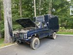
Like the @Mad Texan suggested, pictures under the hood might be useful to your light problem. Pictures of the truck itself would make the rest of us happy. We are definitely "Picture Hounds" here.

Again, welcome to the group.
 

ezgn

Well-known member
650
1,039
93
Location
Lake Elsinore Ca.
I recently picked up a M1010 truck and had some questions regarding the wiring for the lights. It seems like some things have been modified on the truck, so I am trying to understand what's been done. It almost seems that all the 12V wiring has been eliminated and everything is set up to be at 24V... is that something people do instead of 12V conversion? The lower alternator does not seem to be working at all right now(like 0.5V when running at the positive terminal with the pos wire disconnected), but the positive wire for it runs through a to a terminal on the firewall (im guessing the volt-meter) and directly to the 24V bus. The top alternator has a switch wired to it so you can turn it on/off, and also just goes to the 24V bus. So there doesnt seem to be a 12V charging system like Ive read with the DUVAC.

There also does not seem to be a 12V bus at all, the only wire on the positive terminal of the front battery (the "12V" one) is the one going to the negative on the back battery. I would expect there to be a wire here that runs to some sort of 12V bus like I've read online, is that correct?

This all brings me to my recent discoveries where I finally figured out how to get the lights on (for some reason the horn was wired to the service lights on switch, so I had to disconnect that before I could see if the lights worked) and I flicked the high beams on and they turned on momentarily then the headlights and one of the front parking lights went out, seems like the bulbs got burnt out or something...? So my question is are those lights supposed to be 12V or 24V? By turning on my high beams did they get burnt up from getting 24V when its supposed to be 12? but then why would they be working before without high beams on... and why is one of the parking lights still working?

Hope that Is clear enough, Im just trying to get a grasp for how this is supposed to be set up so I can begin to understand how it is modified, any insight you have here would be helpful. Thanks!
If you have a stock CUCV then everything on the vehicle should be 12 volt except for the starter which is 24 volt. I believe with the M1010 there are some differences with the electrical to run the rear equipment, but I believe the main engines electrical system is the same.
 

Mad Texan

Well-known member
Steel Soldiers Supporter
657
1,150
93
Location
Chester County, PA
If you have a stock CUCV then everything on the vehicle should be 12 volt except for the starter which is 24 volt. I believe with the M1010 there are some differences with the electrical to run the rear equipment, but I believe the main engines electrical system is the same.
The electrical panel in the rear is 24v and fed from the bus bar on the firewall. If stock there would also be 24v to the resister for the glow plugs and 24v to the starter. The DUVAC on the M1010 complicates the situation of the wiring for the alternators but can be resolved fairly easily with the plan B mod.
 

Attachments

ethanh100

New member
6
3
3
Location
CT
You probably should start with a few pics under the hood... the 12v bus which only has two connections is on the firewall by the master cylinder.
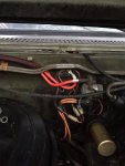
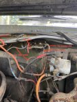
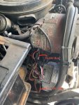
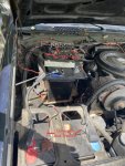
Here is a picture of the 12V bus, which doesnt seem to be 12V at all. There are two wires coming off the bus going into the wiring harness below and one more wire going directly to the back of the fuse panel below the steering column. Then there is a bigger orange wire which runs to the lower alternator (the one that isn't working right now... going to figure that out later...) and then one red wire which runs to the positive terminal on the rear battery, so 24V.

So is there only one thing wired incorrectly right now, being that last wire thats going to 24V but should be going to the pos terminal of the front battery? Should that whole fuse panel below the steering column be at 12V? Are other things being damaged with it being at 24V?

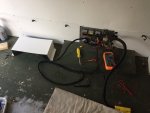
In the pictures you can see a set of wire with a fuse off the front battery, that just runs to an aux switch that is not hooked up to anything right now.

Thanks for all the replies.
 

Attachments

Mad Texan

Well-known member
Steel Soldiers Supporter
657
1,150
93
Location
Chester County, PA
Here is a picture of the 12V bus, which doesnt seem to be 12V at all. There are two wires coming off the bus going into the wiring harness below and one more wire going directly to the back of the fuse panel below the steering column. Then there is a bigger orange wire which runs to the lower alternator (the one that isn't working right now... going to figure that out later...) and then one red wire which runs to the positive terminal on the rear battery, so 24V.

So is there only one thing wired incorrectly right now, being that last wire thats going to 24V but should be going to the pos terminal of the front battery? Should that whole fuse panel below the steering column be at 12V? Are other things being damaged with it being at 24V?

In the pictures you can see a set of wire with a fuse off the front battery, that just runs to an aux switch that is not hooked up to anything right now.

Thanks for all the replies.
First things first are some links:

M1010 Color Coded Diagram

Fuse Box Layout

Second: Is the lower alternator a 12v one? I can't read the numbers on it

Third: The fuse panel should have 12v except for one that is labeled #12 28v

Fourth: The 12v bus is IMG_1535 and the 24v bus is IMG_1537 with the 5 terminals with the Neg bus below with 3 terminals
 

ethanh100

New member
6
3
3
Location
CT
First things first are some links:

M1010 Color Coded Diagram

Fuse Box Layout

Second: Is the lower alternator a 12v one? I can't read the numbers on it

Third: The fuse panel should have 12v except for one that is labeled #12 28v

Fourth: The 12v bus is IMG_1535 and the 24v bus is IMG_1537 with the 5 terminals with the Neg bus below with 3 terminals
Yes the lower one has a 14V regulator. I was having problems with the no charging happening at all and the batteries were dying until I flipped the switch thats been wired to turn the top 28V alternator on, so I am assuming this 14V lower alternator is not operating at all. Is there a good way to diagnose what's wrong with this alternator?

And yes Ive figured out which bus is which, it seems like most of my problems have been caused by the 12V bus being wired to 24V by the previous owner.
 

chevymike

Well-known member
604
470
63
Location
San Diego, CA
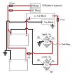
Personally, if you want to keep the 24/12v hybrid system, dump that upper alt for another 12v one like the lower alt in your pic. Then you can wire it up like this, which will charge the batteries correctly, give you 24v for the starting system and 12v for everything else. This is how my M1010 is wired.

Other option is to go 100% 12v and swap the starter to a 12v version. Then wire the batteries in parallel for a 12v system and be done.

This is for the 24/12v system

FB_IMG_1578890324711.jpg
 

Mad Texan

Well-known member
Steel Soldiers Supporter
657
1,150
93
Location
Chester County, PA
Yes the lower one has a 14V regulator. I was having problems with the no charging happening at all and the batteries were dying until I flipped the switch thats been wired to turn the top 28V alternator on, so I am assuming this 14V lower alternator is not operating at all. Is there a good way to diagnose what's wrong with this alternator?

And yes Ive figured out which bus is which, it seems like most of my problems have been caused by the 12V bus being wired to 24V by the previous owner.
Personally, if you want to keep the 24/12v hybrid system, dump that upper alt for another 12v one like the lower alt in your pic. Then you can wire it up like this, which will charge the batteries correctly, give you 24v for the starting system and 12v for everything else. This is how my M1010 is wired.

Other option is to go 100% 12v and swap the starter to a 12v version. Then wire the batteries in parallel for a 12v system and be done.

This is for the 24/12v system
I would say that you are on the right path that your issues were created from incorrect wiring. Getting the bottom alternator (12v) checked out at an alternator shop or an auto parts store would be a good start as wiring issues may have let the magic smoke out.

As suggested following the Plan B Mod method of upgrading the charging system of the M1010 will make it very reliable. The decision of 12v or 24v is up to you. I made the choice to keep 24v and utilize the electrical panel in the box.
 
Last edited:
Top
AdBlock Detected

We get it, advertisements are annoying!

Sure, ad-blocking software does a great job at blocking ads, but it also blocks useful features of our website like our supporting vendors. Their ads help keep Steel Soldiers going. Please consider disabling your ad blockers for the site. Thanks!

I've Disabled AdBlock
No Thanks