• Steel Soldiers now has a few new forums, read more about it at: New Munitions Forums!

  • Microsoft MSN, Live, Hotmail, Outlook email users may not be receiving emails. We are working to resolve this issue. Please add support@steelsoldiers.com to your trusted contacts.

M1010 Work Log

joshuak

Active member
747
214
43
Location
Slower shore, DE
Dash

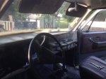
The pirate themed dash left from the PO was one of the first things to go, wrenches before wenches.

IMG_1461.jpg IMG_1492.jpg

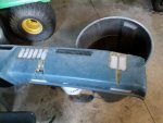
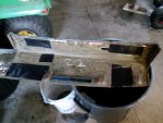
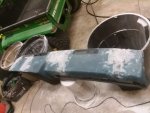
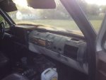
A coworker donated a dash from a square body he was scrapping, it needed some love, but can't beat the price. I cut the vinyl back along the edges of the cracks until it was flush with the surface and taped the back with Gorilla tape.

IMG_2965.jpg IMG_2969.jpg

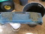
Then I filled in the voids with medium length fiberglass filler from Napa, hit it with a DA sander and a couple of coats of Krylon Fusion spray paint.

IMG_2966.jpgIMG_2967.jpgIMG_2968.jpg

After some baking and freezing cycles in the truck it has developed some cracks, but for under $50 and the wife doesn't mind, I'm happy.

IMG_2958.jpg
 

joshuak

Active member
747
214
43
Location
Slower shore, DE
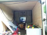
Working on the box

I don't have big plans to build out the rear box just yet, I'm leaning towards keeping an empty space where I can add and remove depending on the activity, again undecided.

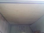
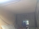
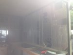
However, there was some water intrusion that I needed to find the source of and stop, while I was there I figured it would be a good time to start insulating.


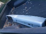
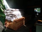
After many rivets, I was able to remove insulation and found the source of the leak.

IMG_2981.jpgIMG_2982.jpgIMG_2962.jpg

I like manuals, I followed instructions for "Repair of Small Skin Puncture" paragraph 4-10 of TM 10-5411-207-14 (S280 shelter), and repaired the hole in the roof.

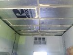
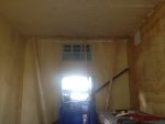
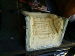
I used 2" rigid insulation between the ceiling cross members, filled in the cracks with expandable foam, then glued (PL300) a 1/2" piece of rigid foam to underlayment board and screwed that in to the cross members.

IMG_2980.jpgIMG_2979.jpgIMG_2978.jpg

For the sides I'm planning on doing something similar, but using 1" rigid insulation for the sides as opposed to 2" and maybe 1" as opposed to 1/2" glued to the underlayment board, not sure...

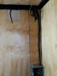
Electrical will run through exposed conduits and initial thoughts on coating for the wood is either paint or a linseed oil/varnish mixture.
 

Mad Texan

Well-known member
Steel Soldiers Supporter
657
1,150
93
Location
Chester County, PA
I've read enough on the site about the Duvac charging system to know I want no part of it. When I purchased the truck it had been converted to 12v, I want 24v. I opted to imitate what ChevyC60 did here.

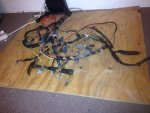
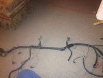
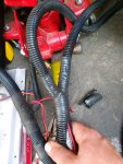
So, I pulled the engine side wiring harness and started cleaning up and removing Duvac related wires.

View attachment 670203 View attachment 670204
I keep looking at these pictures and dreading this...
 

joshuak

Active member
747
214
43
Location
Slower shore, DE
I keep looking at these pictures and dreading this...

The good thing is that's an optional step, most folks just tape the ends up and tuck away I believe.

But if you go for it, I will say this: it's a fun project, if done correctly should give you peace of mind, great way to learn the location of engine compartment electrical connections and it looks good IMO.

Before and after.

IMG_1519.jpgIMG_2172.jpg
 

Mad Texan

Well-known member
Steel Soldiers Supporter
657
1,150
93
Location
Chester County, PA
I agree with it looking better but for me it's more an OCD thing. I worked on cars and trucks for many years, from beaters to restorations. I look at the wiring in my truck and there are loose wires and a wirenut on one by the alternator and I just see problems down the road. I will clean mine up like you did but currently want to get it running again with what is there before ripping into that. The alts are sitting in my cart on fleabay but I haven't pulled the trigger yet. Hopefully get the inner fender in today and get my front battery tray repaired.
 

joshuak

Active member
747
214
43
Location
Slower shore, DE
I agree with it looking better but for me it's more an OCD thing. I worked on cars and trucks for many years, from beaters to restorations. I look at the wiring in my truck and there are loose wires and a wirenut on one by the alternator and I just see problems down the road....
CDO (arranged alphabetically) or not, wirenuts are probably not the right tool for the job :razz:. I've found some stuff like that as well.

... I worked on cars and trucks for many years, from beaters to restorations... I will clean mine up like you did but currently want to get it running again with what is there before ripping into that...
I look forward to seeing your work sir, and I completely understand that last part, mine was a lawn ornament for a good part of a year, I'm thankful for understanding neighbors.

The alts are sitting in my cart on fleabay but I haven't pulled the trigger yet. Hopefully get the inner fender in today and get my front battery tray repaired.
One step at a time, good luck with the projects.
 

joshuak

Active member
747
214
43
Location
Slower shore, DE
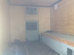
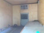
Worked some more on insulating the box. A picture in post 22 shows polystyrene (pink) in the wall, it's what HD had when I went, so I put it up. Bad idea, turns out the working temp of polystyrene is only 165 F, compared to operating temp of polyisocyanurate (pictured in the roof) is 270F.

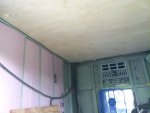
I removed the offending insulation and replaced with 1" polyiso boards between the studs, and finished it like the roof with 1/2" insulation glued to underlayment board and that screwed to the studs.

IMG_2988.jpg

Passenger side, keeping the heater and associated bench for now.

IMG_2987.jpg IMG_2990.jpg


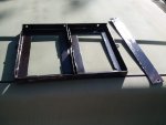
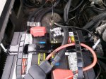
Put a battery tray together from metal removed from the ambulance shelves, fits on the front tray, simple but functional.

IMG_2991.jpg

Neither is finished, but it's moving along.
 

joshuak

Active member
747
214
43
Location
Slower shore, DE
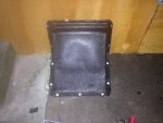
I don't know if it works or not. I just wasn't ready to commit on it's removal, rent is affordable.

The fuel supply lines were in bad shape and I have not replaced them nor did I replace the T in the main fuel line that feeds the pump.

The only part of the system that I've tested is the pump and that works. If and when I get it up and running, it will be used when the vehicle is stationary and fuel will be supplied by Jerrycan or similar.
 

joshuak

Active member
747
214
43
Location
Slower shore, DE
More box work.

I used Great Stuff cracks and gaps to fill in the perimeter where the walls and ceiling meet, didn't need much, a little goes a long way. Used the same product as an adhesive for the last section of ceiling insulation and board.

IMG_3004.jpg

While the can was open, can't imagine trying to reuse one, I covered the fuel filler cover with a 1" layer or so and trimmed the excess.

IMG_3009.jpg

Covered the walls and ceiling with 2 coats of polyurethane exterior varnish. Cleaned, painted and reinstalled the aluminum trim around the upper corners.

IMG_3005.jpgIMG_3006.jpg

Still plenty of work left, but it's coming along.
 

joshuak

Active member
747
214
43
Location
Slower shore, DE
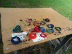
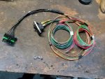
I disassembled the ambulance body wiring harness and removed wires from it belonging to circuits that would no longer be used. Many of the lighting fixtures were MIA when I got it and will not be replaced.

From this:

IMG_3040.jpg

To this:

IMG_3039.jpg

And then back to harness:

IMG_3043.jpg

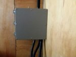
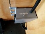
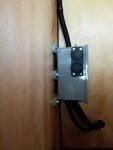
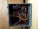
To replace the junction panel that was under the driver side bench, I installed a junction box. I cut down the original aluminum junction panel to fit inside the box and attached components to that, could have gone with a larger box, but at the time I was saving loot.

IMG_3044.jpg IMG_3045.jpg

I kept the door ajar light, heater (I know 24v.), interior dome (changed to LED), blackout light, right and left flood lamps and then added a couple of charging ports.

IMG_3042.jpg IMG_3046.jpg

Also installed the fuel filler cover and the battery tray.

IMG_3035.jpg IMG_3038.jpg

Lot of work ahead, but it's progress. Thanks for checking it out, good day to all.
 

joshuak

Active member
747
214
43
Location
Slower shore, DE
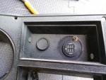
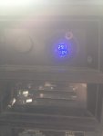
Added a dual voltage voltmeter, it replaced a 12v voltmeter that occupied the original vm spot (truck was converted to 12v when I bought it). I wanted the ability to monitor both 12v and 24v sides and was not willing to relocate the rear door adjar light.

IMG_3080.jpgIMG_3083.jpgIMG_3075.jpg

Original dash is unmolested except for the PO's overspray :-x.


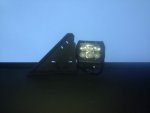
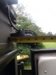
Also, I added some flood lights, I followed Techno's recommendation here, and so far I am pleasantly surprised. One on each side and two in the rear, they are controlled by the buttons on the dash, each one has a relay and a fuse in the rear compartment junction box. I repurposed the GPFU switch to control rear lights. To avoid having them ripped off by the first branch that rubs the side, I built a couple of brush guards, hopefully they work.


IMG_3073.jpgIMG_3081.jpgIMG_3070.jpgIMG_3069.jpg


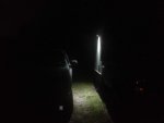
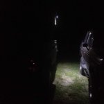
Illumination pattern:

IMG_3078.jpgIMG_3079.jpg


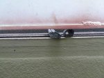
I replaced the weather stripping around the rear door, I used some 3m self adhesive purchased on amazon, on the corners I applied 3m weather stripping adhesive.

Weatherstripping profiles old on the left, new on the right.

IMG_3082.jpg


...
 
Last edited:

joshuak

Active member
747
214
43
Location
Slower shore, DE
Last month I started a few projects on the ambulance, managed to finish one of them and made progress on the others.

The one I finished was replacing the rear marker lights. New sockets and lenses. A simple task by itself but after replacing the sockets I could not get them to work. Long story short, the sockets were not wired as per the diagram, as opposed to being connected to the corresponding turn signal wire (yellow or green) and then to ground, they were connected to the stop/hazard wire (brown) and then to ground, the harness did not look like it had been modified, who knows. I chose to replicate the wiring found on the front marker lights, in order to that, I cut the black wire and connected it to the turn signal wire of the corresponding side. It now lights up with hazard lights, stop lights and turn signal.

Peterson V132R and the electrical diagrams so the above paragraph makes sense.
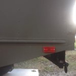
IMG_3122.jpg Service Lighting Circuits Rear M1010.jpgService Lighting Circuits Front M1010.jpg


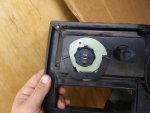
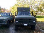
I also removed the AC unit and have temporarily replaced it with lexan bolted to the body with silicone around the edge to seal up the opening and then a piece of plywood bolted to the outer 4 bolt holes to protect the lexan during driving. Easy enough to remove the plywood when I need a window. I am currently undecided as to what to do there, the AC unit will go into storage.
IMG_3111.jpg


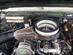
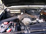
After ordering and reading Volumes 1 and 2 of the 6.2 Diesel Engine from thedieselpage.com, another project I've started is my own version of Swagner Air, named after Dr. Lee Swagner AKA the clevite kid. The basic concept is help the 6.2 breathe by modifying the air intake and adding a larger exhaust, after having done this, turn up the IP a 1/16th or an 1/8th while monitoring the EGTs.

So far I've modified my air intake, by adding 2" inches to its height in order to accept two 3" air filters and opened up to at the inlet to a 4" pipe, Dr. Lee aims his inlet to the front grill, I have a battery tray in the way and I'm not to keen on moving it nor having it get air from there anyway. So, it's currently aimed at the outer fender crumble zone, waiting for a snorkel. Hope the General doesn't mind some Toyota metal underhood. To help support the modified intake I took the rear AC compressor brace off the driver side exhaust manifold and bolted it to the passenger side manifold, then weld a tab to the intake and bolted it to the brace, easily removable.
IMG_3105.jpgIMG_3114.jpg

I'm currently waiting for the machine shop to start/finish? the exhaust flanges, after that I can up the exhaust pipe size to 3" from the manifolds to the exit, install a pyrometer gauge and turn a screw. The screw turning will probably happen after I'm happy with the timing.

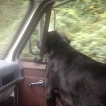
Of all the work done this month, the supervisor liked riding in it the most. We put about 200 miles road time this past month, good stuff.
IMG_3094.jpg


Thanks for reading, good luck folks.
 
Last edited:

cruzer747

Active member
218
145
43
Location
California
I too found the rear wires were not as per diagram... had a lot of cleaning up to do as well as tapping in to turn signal feed for reusing some of the aftermarket lights that were on my rig in the rear (holes were cut so I am stuck with em)
 

joshuak

Active member
747
214
43
Location
Slower shore, DE
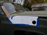
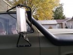
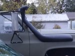
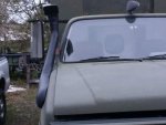
She got a snorkel. I read a Technical article written by Metrodps over on CK5 a few times (link) and did it. K9vic and readyman have shown similar setups here and here. Purchased from Ebay, $80 shipped.

Pictures because it happened:

I did a few things differently from Metrodps, such as: as opposed to making two cutouts, I extended the intake neck on the original one and used that for snorkel placement.

IMG_3138.jpg

Original bend
IMG_3136.jpg IMG_3137.jpg

Other things done differently were: I heated the sand before filling the intake and used two locations to pull from while heating the intake.

IMG_3130.jpg

The result
IMG_3143.jpg IMG_3144.jpg

The bracket is held to the A pillar by nutserts and it is now painted black, I bent the original and added metal to it.

The two nuts closest to the firewall would still be laughing at me if soldier B had not come to the rescue, keep that in mind if your forearms are thicker than your wrists.

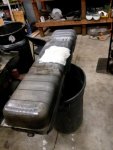
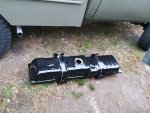
Also, I went ahead and added the NL2 RPO, aka Auxiliary fuel tank.
Junkyard to the rescue for brackets and tank. I played the clean, treat, prime and paint game. Paper towels work well if you want to keep an area moist with Phosphoric acid overnight.

IMG_3117.jpg IMG_3115.jpg

Following this diagram (for the most part), with these components and this is the start of the sub harness.

RPO NL2.jpg IMG_3141.jpg IMG_3142.jpg


Plenty of work to do yet, but having fun doing it. Thanks for following along, good luck with your projects.
 
Last edited:

Keith_J

Well-known member
3,657
1,323
113
Location
Schertz TX
Nice work. Fascinated by the engine mods..I want to turn up the injection quantity in my 1031 and add water injection to keep piston temperature down. But increasing air flow seems to be the first level in power increase so when I pull the intake to change the IP, manifold to gasket to head matching will be done.
 

joshuak

Active member
747
214
43
Location
Slower shore, DE
Thank you. I'm not trying to build a fire breathing monster, I know the 6.x is the wrong platform for that, I'm just trying to help it out.

With the intake mostly wrapped up, next on the list, if there was one, is the exhaust. The idea there is to use a flange to clear the 1 7/8" diameter limitation on the exhaust manifolds and attach 2 1/2" pipe directly to the manifold via the flange and after a few inches bump it up to 3" and carry that on back. I'll place the egt gauge in that 2 1/2" section probably DS.

I'm eagerly following along your RV tug thread looking forward to seeing what you do and how you do it. Porting heads and manifolds just makes sense as long as your there.
 

Keith_J

Well-known member
3,657
1,323
113
Location
Schertz TX
I don't have to change the injection pump!! It runs perfect now, another hat tip to Diesel Mechanic in a Bottle. I have a gallon jug on my shopping list with the intake gaskets and port burrs for my die grinder.

The mufflers and tail pipes on my 1031 are fine, the front pipes are nearing the end of their life so those needs swapping. Larger diameter with smoother bends will fit the bill, I have a tube roll so this is possible DIY. It will be TIG welded as I am comfortable down to 0.035" thickness. Might as well do 409 stainless too.
 

joshuak

Active member
747
214
43
Location
Slower shore, DE
Keith_J thanks for the smile this morning, happy to read that that you were able to resuscitate your IP. You say another hat tip, so you're happy with the product, do you use it only for corrective maintenance or preventive as well? Also good news on your exhaust, not having to change it all saves resources (time and $) and I'm all about saving both.

Now as to matter of how you are going to fix your exhaust leads me to request the following:
If you have time would you please update your RV tug thread with the work you've done to it?
The reason I ask this is that in the last couple of days I've read on different threads about all the work you've done to it, such as fixing both the gen. and air compressor, adding air bags, HD hitch, loading it up with cool tools which I know you know how to use because your skills are sometimes on display over on Mckoen's threads (totally cool that you lend a hand). So, it would make it much easier to follow along, ask questions, reference it later, admire your skills, etc. etc.
Regardless in which thread, I appreciate you taking the time to post and if it's easier to post here, have it :beer:.


Back to the '10, replaced a switch on the NP208, 4x4 dash light works now.

IMG_3128.jpg

Worked some more on the aux. fuel tank wiring. Switch placement, I'd hate for people to think my truck is modified.

IMG_3147.jpg


Exhaust manifold flanges came in!
IMG_3162.jpg


Happy Thanksgiving folks, wishing everyone the best.
 
Last edited:
Top
AdBlock Detected

We get it, advertisements are annoying!

Sure, ad-blocking software does a great job at blocking ads, but it also blocks useful features of our website like our supporting vendors. Their ads help keep Steel Soldiers going. Please consider disabling your ad blockers for the site. Thanks!

I've Disabled AdBlock
No Thanks