• Steel Soldiers now has a few new forums, read more about it at: New Munitions Forums!

  • Microsoft MSN, Live, Hotmail, Outlook email users may not be receiving emails. We are working to resolve this issue. Please add support@steelsoldiers.com to your trusted contacts.

M1031 to RV tug..

Keith_J

Well-known member
3,657
1,323
113
Location
Schertz TX
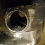
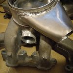
Intake side is nearly complete. Just need to o-ring the boost tubes, figure out the angles and bends and fit the air ducts. Two 16 gauge aluminum butt welds, these are gravy compared to welding on castings

Added two more bolts for the top hat to manifold. Tap for the 7mm X 1 thread is on back order. Need to fab extensions for air filter mounting, these are steel.20220522_224616.jpg
 

Attachments

Keith_J

Well-known member
3,657
1,323
113
Location
Schertz TX
Just looked, I only have an M6 and an M8, sorry.
Odd number size, below 6mm are common. I've triple checked size and pitch. The Banks adapter uses only 2 for holding back around 300 pounds of force due to 12 PSI boost. Using 4 sounds better based on shear on the cast aluminum threads. Plus less deformation in the 1/4" aluminum. I'm using allowable stress of 12,000 PSI on all pressure parts.
 

Keith_J

Well-known member
3,657
1,323
113
Location
Schertz TX
M7? Odd choise? Very uncommon. Why not M6 or M8?
The stock air cleaner studs are indeed M7X1. I suppose the designer had used a 1/4 inch and was told to make it metric because that was the managerial edict of the day. Didn't know preferred sizes.

While I could have gone to 5/16", it would require all new studs and wing nuts. I found the M7x1 bolts at a local hardware store. Only the tap is my source issue. It will be here in a day or three.
 

wrenchturner6238

Active member
Steel Soldiers Supporter
333
29
28
Location
Beaver Oklahoma
The stock air cleaner studs are indeed M7X1. I suppose the designer had used a 1/4 inch and was told to make it metric because that was the managerial edict of the day. Didn't know preferred sizes.

While I could have gone to 5/16", it would require all new studs and wing nuts. I found the M7x1 bolts at a local hardware store. Only the tap is my source issue. It will be here in a day or three.
Looks like a really neat project. Nice welding and fab work
 

Keith_J

Well-known member
3,657
1,323
113
Location
Schertz TX
Tap and die set came in. I had drilled holes to 0.234" as that is what my fractional index has, 15/64". 6mm is called for which is .2362". Regular bar soap is my tap lube of choice for aluminum, tapped almost as easy as installing a bolt. Chips from cast manifold are tiny so threads are sharp and full.

I rolled and welded some 1/8" bar into cylinders for the CDR ports, these will be welded into the top hat once final fitting is complete. These tubes are interference fit with the stock brass barbed fittings.
 

Keith_J

Well-known member
3,657
1,323
113
Location
Schertz TX
Well, I was mistaken. Air cleaner studs are 8mm, 1.25 pitch. They were so dirty my thread gauges and actual M7x1 bolts threaded and held until heat from welding and cleaning..so I had to change the design just a bit.

I even had the tap on hand. Just need to test the CDR integration which has to wait for final turbo placement.

Found some gasket material and fabricated the top hat to intake manifold. This holds boost pressure with top hat and 4 bolts, 2 each of 8mm and 7mm. The 8mm are extensions for the stock air cleaner studs. Yes, that air filter is good enough for 700 cubic feet per minute which is over 15 PSI boost. My design is 10 PSI maximum.
 

Keith_J

Well-known member
3,657
1,323
113
Location
Schertz TX
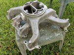
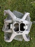
The modifications to the intake manifold done, a full cleaning was necessary as there was remaining engine gunk in the runners which will trap a few of the thousands of aluminum shavings. And a good exterior cleaning is also needed as this was a used take off from Hillbilly Wizard. All the mounting bosses for the rear fuel filter mounting were removed for clearance of the top hat funnels and CDR system. Each soak of engine decreased was washed into a tub to collect all debris to assure no chips remain. 20220604_191043.jpg
 

Attachments

Last edited:

Keith_J

Well-known member
3,657
1,323
113
Location
Schertz TX
One crucial part of the variable nozzle turbo system is turbo control. These CKOs are Garrett generation 2 designs which means vacuum actuated vanes. Vacuum signal is controlled by a 120 Hz pulse width modulated valve, vacuum increases with increasing duty cycle.

Since I don't have to worry about EGR, MAF or NOx limits, sole boost variables are throttle position and boost. For throttle position, I have a stock GM TPS 10137417 which is for a DB2 pump and 4L80E. 0 to 5 volt signal with Vmax at wide open. For boost pressure, I have a 2.5 Bar absolute 0-5 volt sensor. I plan on running this in reverse with 0 volts at 2.5 Bar ( 21.5 PSI gauge).
So with these two inputs, I can use a simple op amp PWM circuit to drive the vacuum control. At low throttle, there is no need for boost so the low voltage from the TPS creates a low duty cycle in the PWM circuit. Open the throttle, TPS voltage goes to 5 and duty cycle of PWM goes to 99%. Vacuum increases, closing vanes and spooling turbines. Manifold pressure increases dropping MAP voltage to the desired set point at 10 PSI. This all has to be bench tested and field adjusted.
3201fig01.gif

Basically, vanes will be closed (more boost) by increasing TPS voltage. To open vanes (reduce boost), a negative voltage from MAP sensor will be summed with TPS voltage. How? Stock 24 volt system is very helpful here. With isolated ground for this control system. Using the back battery negative for the ground of the boost control network, front battery voltage is now a negative 12 volts.
 
Last edited:

Keith_J

Well-known member
3,657
1,323
113
Location
Schertz TX
Back to the variable geometry turbine control..gradually remembering control theory, it looks like I know enough to create a proportional, integral and derivative control using operational amplifier chips..an analog computer.
Proportional control is simply throttle position sensor, 0 to 5 volt signal. Then the integral of the error signal, again 0 to 5 volts, is simply boost pressure.
 

Keith_J

Well-known member
3,657
1,323
113
Location
Schertz TX
Looks like I will replace the vacuum regulating valve on the IP throttle shaft with the 4l80 TPS to control VNT vanes. But this TPS will also control the THM400 with yet another PWM driven vacuum valve. This offers a bit of shift point tuning control..
 

Keith_J

Well-known member
3,657
1,323
113
Location
Schertz TX
I've been experimenting with the variable geometry turbocharger control system. These turbos use variable vacuum to set vane position. Vacuum is controlled by a 3 port solenoid valve used on Europe vehicles. This valve uses duty cycle from 30 to 70 percent which sets vane position from closed to full open.

To provide proportional control, a throttle position sensor mounted to the IP gives 1 volt closed, 5 volts full open with voltage linearly varying. This sets the desired condition, boost which increases to 10 PSI depending on throttle.

Now this will result in over boost and excessive exhaust pressure + restriction. So the voltage signal should be moderated by what is called negative feedback. This will come from a boost pressure sensor plus another minor negative feedback from exhaust pressure. Both pressure sensors are 0 to 5 volt output types.

The 0 to 5 volt signal will not directly control the vacuum valve, this is driven by a pulsed signal, the percentage of on time is proportional to the 0 to 5 volt signal using a pulse width modulated power transistor (MOSFET).

The circuit is already designed, I have a previously built circuit which I modified to a frequency of 23 Hz which testing showed is about correct.

I did a little test, showing an interesting hunting type output but average position can be controlled from wide open to full closed with PWM varying from 33 to 67 %, a range supported by factory controller data maps. I'm not concerned about the vane hunting as this will keep vanes moving, preventing soot buildup.

The complete control system uses less than 1/2 ampere. It is very quick acting so the goal of near instant 10 PSI boost with turbochargers is within reach. Like a twin screw supercharger but without the 50 Hp power consumption. Better than a GMx turbo as exhaust manifold pressure is controlled.
 
Top
AdBlock Detected

We get it, advertisements are annoying!

Sure, ad-blocking software does a great job at blocking ads, but it also blocks useful features of our website like our supporting vendors. Their ads help keep Steel Soldiers going. Please consider disabling your ad blockers for the site. Thanks!

I've Disabled AdBlock
No Thanks