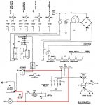
No, on military genset diagrams DS typically means 'light bulb' while S means 'switch'. If you reference the above wiring diagram extract, you will see that it has DS2 as a light bulb (the circle with the loop inside) and S3 as the toggle switch on the panel, but Door Switch is written out as the NC button switch that turns the light off if you close the cabinet door with S3 left on. Since there's an S2 and S3, I'm assuming the door switch is S1... but it's not labeled as such on the diagram.
It is possible that DS1 is mislabled instead of being labeled F1 for fuse or something else since component DS1 includes a diode and a fuse, but then where is the other light since there's a DS2... frustratingly odd compared to the MEP wiring diagrams I worked with when I was in.
Anyway, long story short, the MEP troubleshooting section (since there is NO electrical troubleshooting in this manual) states that if the unit does not build voltage on startup, the field needs to be flashed. Either the fuse is blown, causing the automatic field flash circuit to not function, or the exciter field is too weak to flash with a short application of 12V because it's been idle so long and it needs a longer pulse to begin voltage generation.
In a MEP, you just hold the start switch in the START position until the voltage comes up since there is a starter cutout that prevents you from burning the starter up after the engine passes cranking speed but it doesn't look like this unit has that safety feature, so a manual field flash is in order by jumping 12V from the battery to terminal 5 of the voltage regulator terminal board, which is conveniently located beside the battery.
Later,
Joe


