• Steel Soldiers now has a few new forums, read more about it at: New Munitions Forums!

  • Microsoft MSN, Live, Hotmail, Outlook email users may not be receiving emails. We are working to resolve this issue. Please add support@steelsoldiers.com to your trusted contacts.

M1078A1 Caterpillar pin outs on computer schematic

Lugnuts

Active member
Steel Soldiers Supporter
307
234
43
Location
Myakka City, FL
I really did a search because I had seen where someone had written in about a no start on their engine. I could not find it and I knew at the time I should save it but... So I am asking if I could borrow a cup of schematic for the engine computer so as to check for power and grounds. Please and thank you
I should also ask that if this a common problem maybe someone has an experience or suggestion to throw my way? appreciate it!
 

GeneralDisorder

Well-known member
Steel Soldiers Supporter
1,951
5,044
113
Location
Portland, OR
Which engine?

If it's a 3126B, check the jumper harness that the military installed to delete the deprecated EMI filter box near the ECM. The chassis side connectors and the jumper harness itself are prone to water intrusion and anytime I see these I delete them entirely. Cut out the chassis side connectors and splice the wires directly. There's one power and one ground coming in and going out. Don't mix them up or you will damage the ECM. Each of them feeds two pins on the ECM. Two ground pins and two constant 24v battery positive pins.
 
Last edited:

Lugnuts

Active member
Steel Soldiers Supporter
307
234
43
Location
Myakka City, FL
Which engine?

If it's a 3126B, check the jumper harness that the military installed to delete the deprecated EMI filter box near the ECM. The chassis side connectors and the jumper harness itself are prone to water intrusion and anytime I see these I delete them entirely. Cut out the chassis side connectors and splice the wires directly. There's one power and one ground coming in and going out. Don't mix them up or you will damage the ECM. Each of them feeds two pins on the ECM. Two ground pins and two constant 24v battery positive pins.
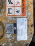
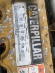
It is a 3126/ Checked with Caterpillar/ It is not a B/ Thanks for responding/
By the way-would that schematic be the same as a civilian designated 3126?
 

GeneralDisorder

Well-known member
Steel Soldiers Supporter
1,951
5,044
113
Location
Portland, OR
It IS a 3126B. That's all the military used in our trucks (besides the 3116 and C7 of course) CAT is often confused with military serial numbers and in any case it doesn't really matter. The chassis side pinout is the same and I believe pretty much the same on the C7 as well.

Since all 3126's use the same computer - civilian or military - they all have the same pinout.
 

Lugnuts

Active member
Steel Soldiers Supporter
307
234
43
Location
Myakka City, FL
It IS a 3126B. That's all the military used in our trucks (besides the 3116 and C7 of course) CAT is often confused with military serial numbers and in any case it doesn't really matter. The chassis side pinout is the same and I believe pretty much the same on the C7 as well.

Since all 3126's use the same computer - civilian or military - they all have the same pinout.
Do you happen to have such the pin out?
 

GeneralDisorder

Well-known member
Steel Soldiers Supporter
1,951
5,044
113
Location
Portland, OR
Do you happen to have such the pin out?
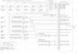
It's spread out all over the diagrams. Here's the engine side of the 3126B:

CATF01_large.jpg

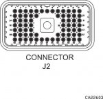
Both connectors (J1 and J2), share the same 70 pin numbering. This is looking at the back of the chassis side - so as if you are staring at the allen bolt that retains the connector to the ECM:

ca22603_large.jpg

The chassis side wiring is part of the truck schematic. You can find a selection of the A1 through A1R schematics here:


Lugnuts

Active member
Steel Soldiers Supporter
307
234
43
Location
Myakka City, FL
So I tested my wiring and found I had the correct power and grounds. Then I checked to see if I had continuity between my ECM connection and Data Port. I called Caterpillar and found out that they could Bench Test my existing ECM to see if it has life.

Now my question is since these ECM's have a known failure problem (or maybe I am reading false articles) are there any alternatives, or is the best thing to do is get another Caterpillar ECM? Is there a reputable refurbishing crew to repair these?
 

Attachments

GeneralDisorder

Well-known member
Steel Soldiers Supporter
1,951
5,044
113
Location
Portland, OR
So I tested my wiring and found I had the correct power and grounds. Then I checked to see if I had continuity between my ECM connection and Data Port. I called Caterpillar and found out that they could Bench Test my existing ECM to see if it has life.

Now my question is since these ECM's have a known failure problem (or maybe I am reading false articles) are there any alternatives, or is the best thing to do is get another Caterpillar ECM? Is there a reputable refurbishing crew to repair these?
How/what instrument did you use to test for power and ground? If your answer is a DVOM, the go back and test the power and ground circuits properly with them loaded. Use at least a 2 amp test light and check for voltage drop. DMM/DVOM is a waste of time for testing. Won't tell you shit. I say this for VERY direct reasons......

The 3126 trucks have a habit of the main battery + and ground circuits specifically for the ECM failing due to a deprecated EMI suppression box hanging off the back of the ECM mounting bolts - these were bypassed but the connectors used for the box on the chassis side as well as the bypass harness connectors themselves were TRASH and virtually always have water intrusion and corroded connections. Have you visually inspected this harness (actually disassemble the connectors) or deleted it?

Also - I bench test and program ECM's for forum members and others routinely. The CAT dealer won't do any re-rating for our trucks but I can and I can clone your ECM (if it's working) to a used ECM for a spare, etc. These ECM's are CRAZY expensive from CAT but are all over ebay from school busses, etc.
 

Lugnuts

Active member
Steel Soldiers Supporter
307
234
43
Location
Myakka City, FL
How/what instrument did you use to test for power and ground? If your answer is a DVOM, the go back and test the power and ground circuits properly with them loaded. Use at least a 2 amp test light and check for voltage drop. DMM/DVOM is a waste of time for testing. Won't tell you shit. I say this for VERY direct reasons......

The 3126 trucks have a habit of the main battery + and ground circuits specifically for the ECM failing due to a deprecated EMI suppression box hanging off the back of the ECM mounting bolts - these were bypassed but the connectors used for the box on the chassis side as well as the bypass harness connectors themselves were TRASH and virtually always have water intrusion and corroded connections. Have you visually inspected this harness (actually disassemble the connectors) or deleted it?

Also - I bench test and program ECM's for forum members and others routinely. The CAT dealer won't do any re-rating for our trucks but I can and I can clone your ECM (if it's working) to a used ECM for a spare, etc. These ECM's are CRAZY expensive from CAT but are all over ebay from school busses, etc.
Alrighty! I tested my circuits with a light but not a 2 Amp light. It being an LED Snap On test light for computers. So I know it wasn't drawing amps. My next question is what doe EMI stand for and what does it do? It was hanging there but already had the connection removed. I take it from a previous post that it is Positive and Negative supply wires for the computer? I will test that, thank you. I will also contact you when I find if this computer is alive or dead. Do you repair them? Also since you seem to be well informed of the situation, what Circuit Breakers feed the ECM? And is there anything else on the matter that you would like to enlighten me on? Thank you!!!
 

GeneralDisorder

Well-known member
Steel Soldiers Supporter
1,951
5,044
113
Location
Portland, OR
Ok. Step one - hold onto that LED test light so you can shove it up the Snap On guy's backside where it belongs. Those are USELESS in my honest personal opinion. They are toys at best but are actually going to misdirect your diagnostic process by telling you that you have voltage but without any indication of the circuits ability to deliver usable current.

I would have to check the schematic on where the ignition power is coming from but I do know it comes into the ECM at pin 70 in the lower right corner (viewed from the back) of the chassis side connectors. Battery +24v comes into pins 52 and 53 and ground is on 65 and 67. Make sure all the power leads can supply +24v to brightly illuminate a 2A test light while using the 65 and 67 ground pins as the ground (disconnected from the ECM of course).

EMI stands for ElectroMagnetic Interference. That box was probably some bad idea fairy's attempt to keep stray electrons from high powered magnetic sources (think: air defense high powered search radar arrays) from making the engine stumble or knocking out the ECM entirely. Ultimately it was a $4,000 magic box that's only real trick was making giant wads of cash disappear into a hole in the ocean created by some CEO's Yacht. They were deleted to no detrimental effect that I have been able to ascertain and haven't reappeared in any later models. The C7 does have better harness shielding and those 70 pin plugs have large alloy covers to protect them that the 3126 doesn't have.
 

Ronmar

Well-known member
3,720
7,251
113
Location
Port angeles wa
two thumbs up... or you can add a plug to that test light and add a 50w halogen fog light(4A@12V) as a load...:) I have an old 100W aircraft light i keep around for 24v testing(same 4A@24v)...

They added a few EMI circuits on these trucks. look at the heater blower, windshield wiper and windshield washer pump electrical circuits. I think their intent was to try to lower the electromagnetic emissions from the electric motors when these devices were in operation...
 

Lugnuts

Active member
Steel Soldiers Supporter
307
234
43
Location
Myakka City, FL
Ok. Step one - hold onto that LED test light so you can shove it up the Snap On guy's backside where it belongs. Those are USELESS in my honest personal opinion. They are toys at best but are actually going to misdirect your diagnostic process by telling you that you have voltage but without any indication of the circuits ability to deliver usable current.

I would have to check the schematic on where the ignition power is coming from but I do know it comes into the ECM at pin 70 in the lower right corner (viewed from the back) of the chassis side connectors. Battery +24v comes into pins 52 and 53 and ground is on 65 and 67. Make sure all the power leads can supply +24v to brightly illuminate a 2A test light while using the 65 and 67 ground pins as the ground (disconnected from the ECM of course).

EMI stands for ElectroMagnetic Interference. That box was probably some bad idea fairy's attempt to keep stray electrons from high powered magnetic sources (think: air defense high powered search radar arrays) from making the engine stumble or knocking out the ECM entirely. Ultimately it was a $4,000 magic box that's only real trick was making giant wads of cash disappear into a hole in the ocean created by some CEO's Yacht. They were deleted to no detrimental effect that I have been able to ascertain and haven't reappeared in any later models. The C7 does have better harness shielding and those 70 pin plugs have large alloy covers to protect them that the 3126 doesn't have.
Pin 70 is in fact switched hot. I will find an adequate test light sir. As far as poking the test light in the posterior of the Snap On dealer not worth it. Would it have been better if it was from Harbor Freight?
 

Lugnuts

Active member
Steel Soldiers Supporter
307
234
43
Location
Myakka City, FL
two thumbs up... or you can add a plug to that test light and add a 50w halogen fog light(4A@12V) as a load...:) I have an old 100W aircraft light i keep around for 24v testing(same 4A@24v)...

They added a few EMI circuits on these trucks. look at the heater blower, windshield wiper and windshield washer pump electrical circuits. I think their intent was to try to lower the electromagnetic emissions from the electric motors when these devices were in operation...
Ok. Step one - hold onto that LED test light so you can shove it up the Snap On guy's backside where it belongs. Those are USELESS in my honest personal opinion. They are toys at best but are actually going to misdirect your diagnostic process by telling you that you have voltage but without any indication of the circuits ability to deliver usable current.

I would have to check the schematic on where the ignition power is coming from but I do know it comes into the ECM at pin 70 in the lower right corner (viewed from the back) of the chassis side connectors. Battery +24v comes into pins 52 and 53 and ground is on 65 and 67. Make sure all the power leads can supply +24v to brightly illuminate a 2A test light while using the 65 and 67 ground pins as the ground (disconnected from the ECM of course).

EMI stands for ElectroMagnetic Interference. That box was probably some bad idea fairy's attempt to keep stray electrons from high powered magnetic sources (think: air defense high powered search radar arrays) from making the engine stumble or knocking out the ECM entirely. Ultimately it was a $4,000 magic box that's only real trick was making giant wads of cash disappear into a hole in the ocean created by some CEO's Yacht. They were deleted to no detrimental effect that I have been able to ascertain and haven't reappeared in any later models. The C7 does have better harness shielding and those 70 pin plugs have large alloy covers to protect them that the 3126 doesn't have.
Caterpillar just did contact me with a reply that the ECM was in fact DRT (Dead Right There) Price is 3918.72 plus programming at 350.00/ What would you suggest, not that I can't think for myself but do you refurb and you stated earlier that you do program. I will see what I can rustle up in test lights for the amp load test. Thanks guys
 

GeneralDisorder

Well-known member
Steel Soldiers Supporter
1,951
5,044
113
Location
Portland, OR
I'm working on refurbishing these ECM's. I've got one on the bench right now that has a power supply issue. Not ready to start accepting them for repair just yet. Soon perhaps though.

But it's easy to just grab a working one for $500 to $1000 off eBay and program it. Just need engine serial number, miles/hours and FLS/FTS for the 3126. I can put either the 275 HP or the 330 HP map on them and setup the speedometer for any gear ratio or ECO hubs that you prefer.

I personally don't see the value in LED test lights. I prefer an incandescent test light for test light duties. Diag guys refer to the incandescent test light as the "scope on a rope" - it's a very powerful tool in the right hands. If I have to get into actual voltage measurement I'm going to reach for a DMM and then it's a slippery slope right to the oscilloscope - which are so cheap now you may as well have one in every vehicle. I carry a dual DMM/O-scope in my truck as well as two different amperage test lamps to load circuits. Yes I AM in fact crazy.
 
Last edited:

Lugnuts

Active member
Steel Soldiers Supporter
307
234
43
Location
Myakka City, FL
two thumbs up... or you can add a plug to that test light and add a 50w halogen fog light(4A@12V) as a load...:) I have an old 100W aircraft light i keep around for 24v testing(same 4A@24v)...

They added a few EMI circuits on these trucks. look at the heater blower, windshield wiper and windshield washer pump electrical circuits. I think their intent was to try to lower the electromagnetic emissions from the electric motors when these devices were in operation...
Pertaing to the EMI, is it comprised of capacitors? I kms other units that use capacitors, is that to control the electromagnetic emissions?
 

Ronmar

Well-known member
3,720
7,251
113
Location
Port angeles wa
Pertaing to the EMI, is it comprised of capacitors? I kms other units that use capacitors, is that to control the electromagnetic emissions?
It is probably some form of LC(inductor-capacitor) or RC(resistor-capacitor) filter circuit to direct the expected motor brush noise to ground instead of exciting the wiring like an antenna. i believe it was to lower the electromagnetic signature.

I found another RC filter in the A0 Vehicle Interface Module output speed signal line, but I suspect that one is to suppress center differential lock solenoid PWM control signals on the speed sensor signal line to keep them interfering with the output speed sensor signal back to the transmission. those 2 signals run thru the same wire and transfer case connector and the trans will quickly malfunction without a valid/expected output speed signal...
 

Lugnuts

Active member
Steel Soldiers Supporter
307
234
43
Location
Myakka City, FL
I am sending my ECM to 1enginecontrolecm who is to refurb this for $549. One year warranty. I plan on load test my existing wiring because I am beginning to understand that the units basically burn up because they have a lack of adequate power going to them ie. your home ac burning up because of brown outs, I'll post my findings. Thank you
 
Top
AdBlock Detected

We get it, advertisements are annoying!

Sure, ad-blocking software does a great job at blocking ads, but it also blocks useful features of our website like our supporting vendors. Their ads help keep Steel Soldiers going. Please consider disabling your ad blockers for the site. Thanks!

I've Disabled AdBlock
No Thanks