• Steel Soldiers now has a few new forums, read more about it at: New Munitions Forums!

  • Microsoft MSN, Live, Hotmail, Outlook email users may not be receiving emails. We are working to resolve this issue. Please add support@steelsoldiers.com to your trusted contacts.

M37 Restoration Project - Revived

ab705

Active member
61
192
33
Location
Maine
As mentioned earlier, I want the front and rear turn signal/stop lights to retain their original 'outward' appearance, but I want to increase their visibility when in use. One thing that I plan to do is substitute LED lamps for the original incandescent bulbs. The other thing that I want to experiment with is to repurpose the blackout marker light slot of each light to serve as an additional amber or red light. As you already know, when the original blackout light was in use, it only displayed a pair of small, dim, modified triangles.
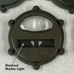
blackout-light-section-of-tail-light.jpg

I removed the parts from the blackout marker light slot, as shown below:
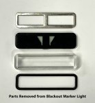
parts-removed-from-blackout-marker-light-slot.jpg

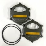
My experiment will be to replace the above parts with a section of a modern red stop light lens for the rear lights and an amber turn signal light lens for the front lights. But before doing that, I wanted to paint the light 'doors' the correct color. The two light doors shown below are for the front turn signal lights. The blackout marker light parts have been removed, and the glass lenses have been masked using a liquid "frisket" instead of masking tape, which was much easier to use than tape because of the shape of the lenses. It's important to allow the masking frisket to dry thoroughly before painting.

light-doors-with-marker-light-pieces-removed-and-white-frisket.jpg

After spraying the light doors with Marine Corps green and allowing the paint to dry for a couple of days, it was easy to peel off the masking frisket:
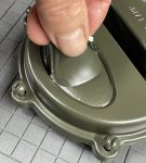
peeling-off-masking-frisket.jpg

Here are the doors after removing the frisket:
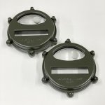
repainted-light-doors-after-removing-frisket.jpg

The next step will be to cut rectangular red and amber pieces out of some modern tail light and turn signal lenses for installation in the blackout marker light slots, and then try some different LED lamps to see how they compare.
 

ab705

Active member
61
192
33
Location
Maine
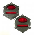
More work on the lights. I cut two rectangular pieces out of an amber turn signal lens for a late-80s Toyota pickup. I also cut two rectangular pieces from a red brake light lens (not shown) for some kind of Honda all-terrain vehicle.

lens-sections-cut-from-turn-signal-lens-smaller-image.jpg

I just installed the amber and red pieces in what were originally the blackout marker light slots in the front and rear light doors. One of the photos below also shows a couple of new square-cross-section O-rings used to seal the light doors to the light bodies. I got the O-rings from McMaster-Carr.

turn-signal-light-doors-with-amber-inserts-smaller.jpg

turn-signal-light-doors-with-red-inserts-smaller-image.jpg

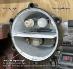
So, just to clarify: The parking and turn signal lamp positions haven't changed from their original positions. The only change is that what used to be the blackout marker light will become an additional turn signal light, which should make the turn signals more visible. It will be the same with the rear lights: The tail light and stop/signal light positions haven't changed from their original positions, but the former blackout marker light will become an additional stop/signal light.

Below is a photo of the interior of one of the front lights with LEDs installed. These aren't the final LEDs, as I'm still experimenting with different types to see what works best. I have a feeling that I won't be making a final decision until I can try them out on the truck in typical day and night viewing conditions., but it's a start, anyway.

turn-signal-light-body-with-LED-smaller-image.jpg

These are a few of the LED lamp types that I'm messing about with. So far, for my M37 lights I'm leaning toward the ones without the built-in projector lenses.

various-led-lamps.jpg
 

ab705

Active member
61
192
33
Location
Maine
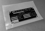
The original ID data plate for my 1954 M37 was missing, so I used Adobe InDesign to create what I think is a pretty accurate facsimile of the original ID data plate design that is appropriate for my truck, as shown below:

data-plate-1954-m37-smaller-image.jpg

There were several steps involved in creating a new etched-aluminum data plate like the original.

First, I printed a mirror image of the design on a special kind of inkjet transparency film. These sheets have a slightly frosted coating on one side, which apparently allows them to accept more ink than an ordinary transparency film. I maxed out the CMYK channels for the black areas in InDesign and set the ink density higher in the printer control app in order to achieve pretty decent opacity.

id-data-plate-flipped-film-positive-smaller-image.jpg

I then adhered a sheet of photoresist film to a carefully cleaned aluminum sheet, working under subdued incandescent light (the film is UV sensitive). It's hard to get this stuff on without trapping bubbles. There is a 'floating it on' technique for doing it with water, but I tried it and didn't like that method, so I just had to refine my pressing and rolling technique on a few practice pieces until I managed to adhere some sheets without bubbles. Here's one of them:

photoresist-film-on-aluminum-before-exposure-smaller-image.jpg

I placed the printed film image emulsion side down on the photoresist film, placed a sheet of plain window glass (not sun-blocking glass) over it, with a piece of foam rubber behind it to keep it pressed tightly against the glass, and exposed it to direct noon sunlight for about 30 seconds.

After exposure I removed the thin plastic protective layer from the photoresist film and 'developed' the photoresist in a mild solution of washing soda, which removed the unexposed (unhardened) portions of the photoresist. I then etched the aluminum with an acid solution (I'm still working on figuring out the optimum formulation, so I won't list it here yet). I had a few trial and error (mostly error) runs before I got a couple of decent results. Here's one of them:

photoresist-film-after-exposure-and-development-smaller-image.jpg

Next, I chemically darkened the etched area with Aluminum Black from Birchwood Casey.

after-ferric-chloride-etching-and-aluminum-blackening-smaller-image.jpg

Soaking the plate in acetone for a few minutes loosened the photoresist and allowed it to be brushed off easily with a soft brush. I then trimmed the edges to the cut lines with a shear.

Here's the end result so far. You can see some reflection from the protective coat of satin urethane that I sprayed on, but the background is actually a nice solid black.

id-data-plate-1954-unstamped-smaller-image.jpg

The etching leaves the letters slightly raised, like the original data plates. I think I'll punch the rivet holes with my Roper-Whitney punch instead of drilling them. I plan to use a 3/32" number and letter punch set to add the serial number and other data. I'll probably make a couple of extra plates in case I mess things up when I'm punching the data onto the plate. In hindsight, I probably should have waited to spray the urethane coating on until after I punch the data onto the plate. I suppose I can dissolve the coating and then re-spray it after punching.

There are a lot of variables involved, and it took about eight attempts before I got a couple of plates that I was satisfied with. I'm sure that with practice I could streamline the process and improve my success rate, but that can wait. On to other tasks...
 
Last edited:

Mullaney

Well-known member
Steel Soldiers Supporter
Supporting Vendor
7,818
19,983
113
Location
Charlotte NC
The original ID data plate for my 1954 M37 was missing, so I used Adobe InDesign to create what I think is a pretty accurate facsimile of the original ID data plate design that is appropriate for my truck, as shown below:

View attachment 929458

There were several steps involved in creating a new etched-aluminum data plate like the original.

First, I printed a mirror image of the design on a special kind of inkjet transparency film. These sheets have a slightly frosted coating on one side, which apparently allows them to accept more ink than an ordinary transparency film. I maxed out the CMYK channels for the black areas in InDesign and set the ink density higher in the printer control app in order to achieve pretty decent opacity.

View attachment 929459

I then adhered a sheet of photoresist film to a carefully cleaned aluminum sheet, working under subdued incandescent light (the film is UV sensitive). It's hard to get this stuff on without trapping bubbles. There is a 'floating it on' technique for doing it with water, but I tried it and didn't like that method, so I just had to refine my pressing and rolling technique on a few practice pieces until I managed to adhere some sheets without bubbles. Here's one of them:

View attachment 929460

I placed the printed film image emulsion side down on the photoresist film, placed a sheet of plain window glass (not sun-blocking glass) over it, with a piece of foam rubber behind it to keep it pressed tightly against the glass, and exposed it to direct noon sunlight for about 30 seconds.

After exposure I removed the thin plastic protective layer from the photoresist film and 'developed' the photoresist in a mild solution of washing soda, which removed the unexposed (unhardened) portions of the photoresist. I then etched the aluminum with an acid solution (I'm still working on figuring out the optimum formulation, so I won't list it here yet). I had a few trial and error (mostly error) runs before I got a couple of decent results. Here's one of them:

View attachment 929461

Next, I chemically darkened the etched area with Aluminum Black from Birchwood Casey.

View attachment 929462

Soaking the plate in acetone for a few minutes loosened the photoresist and allowed it to be brushed off easily with a soft brush. I then trimmed the edges to the cut lines with a shear.

Here's the end result so far. You can see some reflection from the protective coat of satin urethane that I sprayed on, but the background is actually a nice solid black.

View attachment 929464

The etching leaves the letters slightly raised, like the original data plates. I think I'll punch the rivet holes with my Roper-Whitney punch instead of drilling them. I plan to use a 3/32" number and letter punch set to add the serial number and other data. I'll probably make a couple of extra plates in case I mess things up when I'm punching the data onto the plate. In hindsight, I probably should have waited to spray the urethane coating on until after I punch the data onto the plate. I suppose I can dissolve the coating and then re-spray it after punching.

There are a lot of variables involved, and it took about eight attempts before I got a couple of plates that I was satisfied with. I'm sure that with practice I could streamline the process and improve my success rate, but that can wait. On to other tasks...
.
Wow...
That is an amazing process.

.
 

M813rc

Well-known member
Steel Soldiers Supporter
4,242
3,342
113
Location
Near Austin, Texas
Very impressive work!

I did something similar with the front blackout marker lights on my Mighty Mite, since they didn't come from the factory with turn signals.
I cut amber reflector lenses with the focus circle in the middle to fit the holes, using that type because the light holes were small and the circle intensifies the light output.
I used amber LED bulbs with a built in resistor so the flasher "senses" them as regular bulbs and flashes them.
They are amazingly bright, and very visible in sunlight.

I used Gama Goat style lenses on the back, but having seen how you did the smaller aperture lights, I may have to rethink that and follow your example.

Cheers
 

ab705

Active member
61
192
33
Location
Maine
I used amber LED bulbs with a built in resistor so the flasher "senses" them as regular bulbs and flashes them.
They are amazingly bright, and very visible in sunlight.

I used Gama Goat style lenses on the back, but having seen how you did the smaller aperture lights, I may have to rethink that and follow your example.
Thanks Rory. I probably won't know exactly how well my modified lights will work until I try them in real-world conditions, but on the workbench, they seem to be very bright, with a major, attention-getting increase in brightness between the parking/tail light and the signal light. I tried making a video showing the signal lights going off and on, but the brightness range of the lights is so much greater than the dynamic range of the camera that it really didn't demonstrate how it actually appears to the human eye.

I tried using some amber lens pieces that had a concentric Fresnel pattern, but IIRC, I could see a bright spot from a wider viewing angle with the rounded-rib style pieces that you saw in my post. Of course, there are so many different lens pattern variations, as well as LED shapes/lengths/configurations, that it's hard to make any kind of generalization, but so far, so good. I also have a set of Gama Goat lenses that I can play with when that time comes.

I think the turn signal flasher that I purchased should work with LEDs without having to install a resistor to create a load, although I haven't tried it yet.

Al
 

M813rc

Well-known member
Steel Soldiers Supporter
4,242
3,342
113
Location
Near Austin, Texas
I was stuck using the really small bullet blackout lights, which is why I went with the the lenses I did after some experimentation. Your lenses definitely look like they'll work better for that slightly larger light. They look really good and "stock" with the lights off too, which is important.

I used the resistor LEDs because of the standard military flasher I went with, it is so very obvious under the hood I wanted it to look stock.

Cheers

16 - Copy.jpg 27 - Copy.jpg
 

ab705

Active member
61
192
33
Location
Maine
I started digging out some of my M37 components that have been in storage for years.

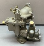
Here's an ETW1 carburetor and governor that I overhauled years ago, complete with re-plated linkage, dichromate conversion coating, new passage plugs, safety lock wire, etc.

etw1-overhauled-2-smaller-image.jpg

etw1-overhauled-1-smaller-image.jpg

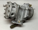
And the fuel/vacuum pump that I overhauled:

fuel-pump-overhauled-1-smaller-image.jpg

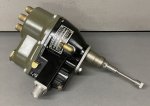
I rebuilt a couple of distributors. Here's one that I kept completely stock:

overhauled-distributor-1-smaller-image.jpg

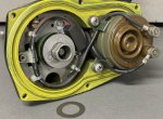
And here's another distributor that I set up for breakerless ignition with a Pertronix Ignitor. Note that I did this MANY years ago, before Pertronix was offering a 24V Ignitor to fit the M37 distributor. I used an Ignitor for another vehicle, and I had to custom-mold the inside of the magnet ring to match the distributor cam and install a resistor, since it was a 12V unit that would be running on 24V. I still haven't tried it in a vehicle yet, but as I recall, it seemed to work fine on the bench.

early-pertronix-custom-conversion-1-smaller-image.jpg

BTW, I recently installed a 12V Pertronix Ignitor and Flame Thrower coil on my 1953 Ford NAA tractor (which has been converted to 12V), and it works great! Highly recommended!
 
Last edited:

Mullaney

Well-known member
Steel Soldiers Supporter
Supporting Vendor
7,818
19,983
113
Location
Charlotte NC
I started digging out some of my M37 components that have been in storage for years.

Here's an ETW1 carburetor and governor that I overhauled, complete with re-plated linkage, dichromate conversion coating, safety lock wire, etc.

View attachment 930332

View attachment 930333

And the fuel pump that I overhauled:

View attachment 930334

I rebuilt a couple of distributors. Here's one that I kept completely stock:

View attachment 930335

And here's another distributor that I set up for breakerless ignition with a Pertronix Ignitor. Note that I did this MANY years ago, before Pertronix was offering a 24V Ignitor to fit the M37 distributor. I used an Ignitor for another vehicle, and I had to custom-mold the inside of the magnet ring to match the distributor cam and install a resistor, since it was a 12V unit that would be running on 24V. I still haven't tried it in a vehicle yet, but as I recall, it seemed to work fine on the bench.

View attachment 930336

BTW, I recently installed a 12V Pertronix Ignitor and Flame Thrower coil on my 1953 Ford NAA tractor (which has been converted to 12V), and it works great! Highly recommended!
.
Wow! Lots of goodies there from your stash pile!
 

Mullaney

Well-known member
Steel Soldiers Supporter
Supporting Vendor
7,818
19,983
113
Location
Charlotte NC
It's been so long, and there's so much stuff stashed away that I'll have to do a complete inventory to remember what I've worked on or replaced.
.
I understand that!
Yeah, having a stash is great.
Remembering what you have is a little more difficult.
 

ab705

Active member
61
192
33
Location
Maine
This is a repair that I did a while ago. The floor under the battery box often rusts out, since it's out of sight and tends to collect dirt and water (i.e., mud). Sorry, no 'before' picture. I cut out that section of the floor, made a template out of thin, stiff cardboard, and used the template as a model for cutting and bending the steel replacement. The photo is looking straight down at the floor with the replacement piece installed. The green dashed line shows the extent of the new replacement piece. I welded it in place with at least 50 plug and stitch welds, sealed the seams with paintable urethane marine sealant, then applied a coat of primer. I was pleased that the metal replacement piece fit well with no further modification. Taking a bit of extra time to create an accurate template helped a great deal.

floor-repair-under-battery-box-smaller-image.jpg
 

ab705

Active member
61
192
33
Location
Maine
I just made another reproduction data plate for my M37. The original brass plate showing transmission, transfer case, and road speed information was barely readable. The original was evidently etched, with slightly raised letters and a chemically blackened background, and I wanted to make the replacement in the same way as the original.

Here's the old ORIGINAL plate after scanning it and making several image adjustments in Photoshop, which enhanced the detail enough to use it as a model for making a replacement.

transmission-plate.jpg

I placed the above image into InDesign and scaled it to actual size, and then re-drew the plate from scratch. I made two versions; one is a pretty accurate rendition of the original, and the other has 'improved' spacing and alignment of the contents. I did the latter just for fun. I'm actually planning to use the more accurate version on my vehicle to be more faithful to the original.

transmission-speed-plate-layout-in-indesign-smaller-image.jpg

I then printed reversed positive films of the design (reversed in order to place the ink side of the film directly against the photoresist film).

transmission-speed-plate-positive-films-smaller-image.jpg

Then I coated a couple of sheets of .025" brass with photoresist film, exposed the photoresist through the above positive films, developed the photoresist to remove the unexposed portions, immersed the brass sheets in a special etching solution, blackened the background with Brass Black from Birchwood Casey, and removed the remaining photoresist with acetone. I also applied a thin clear satin acrylic coating, which deepened the black.

Here are both versions:

transmission-speed-plate-both-versions-smaller-image.jpg

This is the one I'll be using, which is most similar to the original.

transmission-speed-plate-reproduction-2-smaller-image.jpg

Note: I checked the data plate mounting hole spacing against a couple of other M37s, and the spacing varies just slightly, like +/- 1/32" or more. I'll use my original plate as a guide for punching the mounting holes so that I know it will match the existing holes in my dashboard.
 
Last edited:

ab705

Active member
61
192
33
Location
Maine
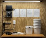
I'm planning to electroplate a lot of small parts for my M37 restoration project, so I cobbled together a plating setup, including an adjustable power supply, a darkroom timer, a couple of heaters, a small circulation pump, various anodes, lead wires, connectors, etc. The bench was sitting unused in our storage unit, and I had a 4-foot LED light that was gathering dust.

plating-bench-1-smaller-image.jpg

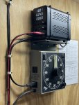
I made a wall bracket for the power supply to keep it up out of the way of splashes and to save countertop space.

I found the darkroom timer on eBay. It's in near-new condition and I picked it up for a small fraction of the cost of a new one.

power-supply-and-timer-smaller-image.jpg

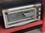
I also bought an inexpensive oven that I plan to use to bake parts immediately after plating to help prevent hydrogen embrittlement.

oven-1-smaller-image.jpg

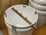
The missus sewed some polypropylene anode filter sleeves for me. These should help keep the solution clear of contaminants and sludge produced by the anodes. I bought a large sheet of the polypropylene material...probably enough to make at least 100 filter sleeves (I'll have to practice using her sewing machine and making some of the sleeves myself to avoid pestering her too often).

Obviously, for larger items, I'll switch to larger buckets or tubs.

small-tank-anodes-filter-bags-smaller-image.jpg

For preparing parts for plating, my approach would depend on the type of part and the condition it's in. It could include various combinations of abrasive blasting, solvent stripping, ultrasonic cleaning, electro-cleaning, alkaline cleaning, acid cleaning/pickling, etc.

I hope to start plating some parts next week. The first batches would be acid-zinc plated with a yellow chromate passivation coating.
 
Top
AdBlock Detected

We get it, advertisements are annoying!

Sure, ad-blocking software does a great job at blocking ads, but it also blocks useful features of our website like our supporting vendors. Their ads help keep Steel Soldiers going. Please consider disabling your ad blockers for the site. Thanks!

I've Disabled AdBlock
No Thanks