• Steel Soldiers now has a few new forums, read more about it at: New Munitions Forums!

  • Microsoft MSN, Live, Hotmail, Outlook email users may not be receiving emails. We are working to resolve this issue. Please add support@steelsoldiers.com to your trusted contacts.

M54 transfer shot.

dmetalmiki

Well-known member
5,523
2,027
113
Location
London England
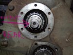
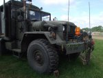
M62- M54 Transfer box Repair problem Help.

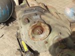
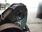
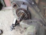
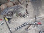
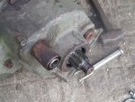
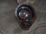
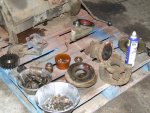
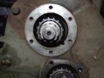
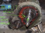
I purchase a used transfer box for my M54A2 camper. It was known to have a problem selecting high ratio, but I got it with another deal. So repairing it whilst running my original noisy one was the option I was planning. (or make one out of the two). Not looking forward to it..you've no doubt seen a dog walking round an oversize bone before making a move on it?. Well picture me today after (solo!) I 'popped' it into a suitable work spot! and 'arranged' it! the right way up, with blocking. Try (visualising) using the fork truck controls at the same time as arranging the blocking support!. (solo!). Now we're at where I am walking round the 'Bone' to figure out where to start!. Tomorrow I will start in earnest. (After some T.M. time). I will post the progress as I go..with the obligatory pictures. (and sore digits, (and sore back ..)) Ho hum...
 

Attachments

Last edited:

dmetalmiki

Well-known member
5,523
2,027
113
Location
London England
Solo? Where were the boys? You usually seem to have ample assistance...
They usually 'help out' at weekends. This week they (were both) taking a part of their 'Duke of Edinburgh' awards. Happy to report they both passed.
Everything is ready for the pull down, I will start loosing things off tomorrow though. But as to doing 'things' under the (ANY) truck nowadays..I like to have someone keeping an eye....just in case the little things happen..(Hernia..heart attack! you know the score..I ain't 26 any more!!)
 
Last edited:

dmetalmiki

Well-known member
5,523
2,027
113
Location
London England
M54A2 M62 Transfer case repair HELP.

I need the advice of someone who has stripped and repaired/overhauled the M54/M62 transfer box.
The T.M. is the usual joke on how to!. I find it absolutely ridiculous that when going through the strip down procedure the instructions keep relating to inconsequential "Parts", and not satisfied with that , promptly list how to Re-assemble those (inconsequential) parts!. Then goes back to NEARLY where you wanted to be in the (progress of) dismantling. List more 'bits to remove AND promptly goes on to reassemble them again! So frustratingly infuriating. As you plough forward to WHERE you want to complete the FULL strip down. (through a maze of "reassemble-reassemble")
THE (only) Logical way to Strip completely, examine replace and repair a component fully, Is to Dismantle it ALL..first, repair and replace , Second. THEN put it back together again, IN logical sequence.
So, rant over, I'm at remove rear drive coupling handbrake drum and parts, Done. air control (air shift), remove drive coupling. Ok, done, forward case, NO chance, (T.M.) Remove front case with Complete with sprags. (T.M. does NOT say with sprags) Only shows a picture Lifting the assembly out of the box WITH the front case. Using a lift/crane whatever. (Idiots!) There is a bearing PRESSED onto the other side of the shaft at the OUTPUT end. Too narrow to get a puller onto it, not good to "hammer on it, we tried with wood and sledge!.
NOT DONE. Anybody actually done this job? and can point me in the correct way forward.
(T.M. joke reads " Remove" shaft!!?? (with the front case!!? ( you guess!))and place in arbour to press the etc!!). The etc. being the Sprag, not the rear bearing.
Yeah,,well. As said, Idiot explanation and instruction.
 
Last edited:

dmetalmiki

Well-known member
5,523
2,027
113
Location
London England
I have them all. This has turned out to be a real pain. (near disaster) as The first show of the season is only 3 weeks away and I have the truck and fork lift blocking the shop.. Hopefully (I Have asked) the moderators to re-name and bump the post to the top.
And of course, All the ones we have are "printed" (copied) as black as it is possible to copy them!.
 
Last edited:

dmetalmiki

Well-known member
5,523
2,027
113
Location
London England
I have tried every puller we have, they are all too large to fit. Is heat (and destroying the bearing) the only way to go?. A grinder will not get at it.
 

dmetalmiki

Well-known member
5,523
2,027
113
Location
London England
Imossible Directions.

Ok, My fault..post without pictures¬ So here are photo's of the offending bearing. I repeat, the T.M. Just remarks " remove input case WITH shaft!!?". ( And therefore the sprag assemblies) "Place in arbour and press off bearing!". NO CAN DO IMPOSSIBLE!.
Referring TO the SPRAG assembly, which is keyed and pressed on. (NO mention of as to HOW the bearing on the output side comes though!.
Anyone who has completed this part of the disassembly's please advise.
 

Attachments

red

Active member
1,988
22
38
Location
Eagle Mountain/Utah
Looks like it's meant to be removed with a specialized puller. Thin jaws that will fit in there.

Couple options I'd try :
1. Take a grinder to a 3 jaw puller and make it able to fit. Apply some heat to the bearing if necessary.
2. Apply heat to the bearing and use a slide hammer (if possible).
Might be able to remove the bearing without damage.
3. Destroy bearing. Cut the cage to remove it and the rollers. Cut the cage outer lip at 2 spots 180 degrees from each other then pry it apart. Setup 3 jaw puller to remove the remaining part of the bearing.
 

Swamp Donkey

The Engineer
Steel Soldiers Supporter
1,450
119
63
Location
Gray, GA
I have not been into one of these before, but I have been into a couple hundred gear reducers for conveyor belts. There are many simularities between the two so I'll give my take on what the TM is wanting you to do.

Most likely the whole cover is put into a press and the shaft is pressed to the inside of the cover. Whatever is on the other end of the shaft, I think you said sprags in your case but a cluster of gears in ours, stays on the shaft until it is out of the cover. The bearing is then left in the cover and is easily removed with a slide hammer.

In our case, the gear reducers are usually rebuilt in place which can be up to 50' in the air. A proper press is not an suitable option at those heights so we normally drive them out with a block of wood and a deadblow hammer. The difference here is that our cases are fabricated where your's is cast. Wailing on the thing might not be a good idea.

The picture of your bearing and the description in the TM make this sound like the same process we go through. Maybe it helps, maybe it doesn't.
 

dmetalmiki

Well-known member
5,523
2,027
113
Location
London England
Thank you, But not in this case. (as) Yes the INPUT case comes off With the sprags, (which then dismantle and fall all over the place! (if you are unlucky). I was half way lucky, Only one sprag fell apart. No matter, it's no problem re-building them back anyway. The input shaft you cannot press, pull, wack!, whatever. It is (as 'declared'(HUMPH!!) in the manual ) "pressed off in an arbour press". YEAH! Well that is where the 'nonsense' comes in. The T.M. Does NOT say "remove" (that bearing on the OUTPUT side) Before Lifting the front case assembly with a crane (or whatever). Though in reality the FRONT case WITH the sprag assembly comes out quite Readily. Either complete, (good) or all in bits (not so good). BUT that carrier (for the sprag assembly(Keyed and pressed in pictures)) HAS to be pressed off with an arbour. (as described in the T.M.).
So, Back to " what about the (totally not mentioned!(in the T.M.)) Bearing on the 'OUTPUT' Shaft.
I may Have to go with cutting it. I will try all suggestions first. Thank you for the inputs to date.
 

dmetalmiki

Well-known member
5,523
2,027
113
Location
London England
O.K. No responses, (that) leads me to the conclusion nobody has stripped one of these transfer cases. (Just replaced them(and no wonder trying to decipher the "T.M.)). So tomorrow I am going to 'Attack' this thing in a methodical and logical sequence. (That the T.M. 'joke' manual! does NOT provide.) I will eventually post up the Proper methodical realistic and logical way to strip down, asses, replace and repair components, And THEN reassemble. In a logical realistic and methodical way.
 

JDToumanian

Active member
1,655
14
38
Location
Phelan, CA
Okay, I had to look in my TM up to the point in disassembly you're at, and studied your pictures... There's a chance I'm not understanding it all correctly yet, but, I THINK the "input shaft" (green arrow in your pic) was supposed to have been removed together with the housing before you took the flange off.

Raise transfer so front output shaft cover faces upward.
Attach chain around flange and lifting device and take UP all slack in chain. Apply tension to flange.
Tighten screws alternately and remove front output shaft cover from front cover. Place front output shaft cover on workbench.
Remove gasket from front cover. Discard gasket.
Using puller, remove flange from front output shaft.
So the removal of the front output cover, using bolts in the threaded cover holes as 'jacking screws' but also with the weight of the transfer case hanging slightly from the flange to help pull, pulls the whole shaft assembly from the bearing on the opposite end, and the whole shaft assembly comes out complete, still inside the housing with the flange on it.

Jon

tc.jpg
 
Last edited:

JDToumanian

Active member
1,655
14
38
Location
Phelan, CA
Maybe I'm confused or maybe my last post was confusing.... In your pic, the green arrow says "input" but so far as I can tell, your transfer case is upside down (the shift rod is near the ground), and what you have labeled as "input" is actually the front output.

Jon
 
Last edited:

dmetalmiki

Well-known member
5,523
2,027
113
Location
London England
Thank you for your time and effort. And, YES, Exactly as I had thought and interpreted. However, My front case came off no problem, LEAVING the SPRAG assembly STILL in position on the shaft. (So with or without that sprag assembly (still mounted or not)) On the shaft, does Not negate the problem of that ###'''** GEAR pressed onto the shaft at the OUTPUT end will not permit removal of the complete shaft. I have just had a 'Thunk' (same as as think but more intense! and inspirational) {from your schematic} I will report back in a couple of hours.
 
Top
AdBlock Detected

We get it, advertisements are annoying!

Sure, ad-blocking software does a great job at blocking ads, but it also blocks useful features of our website like our supporting vendors. Their ads help keep Steel Soldiers going. Please consider disabling your ad blockers for the site. Thanks!

I've Disabled AdBlock
No Thanks