• Steel Soldiers now has a few new forums, read more about it at: New Munitions Forums!

  • Microsoft MSN, Live, Hotmail, Outlook email users may not be receiving emails. We are working to resolve this issue. Please add support@steelsoldiers.com to your trusted contacts.

M939 winch install (Pics & Video)

HASSON1911

Member
748
24
18
Location
roseau/mn
Sorry, I didn't take pics. They are the 2 rear most bolts on both frame extensions. I just made a simple template off of the extensions referenced from the two bolts that hold the cross member for the hood. I drilled the holes(1/2 inch) and when the extensions were in I just ran the drill in them again to finalize the lining up of the holes. I also mounted the entire assy as one piece. The winch, frame extensions, and bumper was all assembled as one. I also used a tow truck boom to single point lift the assy and that allowed us to manhandle/maneuver the assy into the frame. I think that worked a little easier than a forklift.
Interesting take, how did the extensions fit into the chassis, I imagine if everything was loose you had play to make it slide in, there are many ways to skin a cat, The fork lift was used to just drop in onto the extensions. we actually threw a chain around the axle and used a come-along, and with little to no force it gently slide back on the extensions, nice and level without worrying about hitting that shield above the drive...probably could have just pushed it back by hand, one of you guys planning on doing an install can report back on that one
 

Gunzy

Well-known member
1,769
66
48
Location
Roy, Utah
With the winch mounting bolts a little loose it slid right in. I was on one side and "soldier b" on the other. A little wiggling and it slid in farely easy.
 

BMS07

Member
212
23
18
Location
Janesville,WI
Does anybody have the model number of the pto? I have a pto that I think is the right one. Trying to find all the pieces to put a winch on my M931A2. Thanks Brad
 

clinto

Moderator, wonderful human being & practicing Deuc
Staff member
Administrator
Super Moderator
Steel Soldiers Supporter
Supporting Vendor
12,596
1,129
113
Location
Athens, Ga.
I have been planning on adding to this thread for a while and since I'm sick and sidelined on the couch, today is it.

Since this thread is titled in a way that makes it always come up at the top for any M939 winch install, I think we're going to consider it the official "how to install a winch into an M939 series truck" thread and I'm going to add a bunch of stuff here that the OP didn't.

A friend of mine brought me this really clean M931A2 to add a winch to and convert to M932A2 specs. He had a complete takeoff winch kit from an M925 or M925A1. He had already installed the winch w/level winder. I did the rest. Up to this point, I had zero M939 winch knowledge, so I had to learn all of this.

I hope that before folks go out in to the world and buy takeoff winch kits, they read this thread. To be honest, it really makes me mad to see all these people, who are either not knowledgeable, or worse (and more likely), unscrupulous on eBay and all the Facebook pages for military vehicle sales selling kits and saying they fit all M939 models. Really makes me mad. Some poor guy is going to buy a kit that won't work for his model and is going to be halfway through the job before he realizes "oh crap, half my donor kit is useless". It takes a lot of self restraint to not post on these people's ads "Hey, you say this fits all models, but it won't fit M932s, any M939A2 model, etc., etc.". The crappy nature of social media would probably just end up with me being flamed anyhoo.

So, the two things you really need to know is that these things are nothing like the older M39/M809 series 5 ton winches or the M44 deuce kits. On the older trucks, you can take a complete winch kit off a wrecker and put it on a dump, etc., etc. They're all the same. These (M939) trucks are not like this, for several reasons. The biggest issue is that the hydraulic tank mounts in a different place on almost every model. The cargo trucks mount on the passenger side, in between the middle tandem and the tool box. The early M932 tractors mount right behind the passenger fuel tank (see images in post #41) and the later M932A1 and M932A2 models mount it on the drivers side, above the frame, right behind the cab. Dump trucks apparently use the reservoir for the dump hydraulics, which is under the bed, because I never found this model in the TM. Wreckers use the giant 80(?) gallon reservoir that hangs on the side of the hoist for the front winch. Weirdo models like the M934, I have no idea.

Dump (M930) reservoir:

684902_6006_353_0001.jpg

Cargo (M925 and I think M928 ) reservoir:

689554_6002_10119_0001.jpg

Tractor (M932A1/M932A2) mount:

531698_6006_353_0001.jpg

And of course, the hydraulic tank itself is specific, since the brackets are welded on them. So it's not like you could just swap brackets. M925 shown on right, M932A1/M932A2 shown on left.

20160921_103516.jpg


Also, beware, on our M925 donor tank, it had a cracked ear from stress. Inspect carefully. I suspect ours isn't the only one out there like that.


Since the tanks go in so many different places, this means all the hoses and pipes are different and specific to your application. These can be very expensive.

The second issue is A2 versus M939/M939A1. The PTO, shift tower, PTO shift cable, PTO shift cable mounting bracket (bolts to the front of the PTO), PTO driveshaft are all A2 specific. The easiest way to identify the A2 PTO is that the upper center bolt is accessed from inside the PTO. The earlier model is an external bolt. The shift tower is A2 specific because of the different doghouse/firewall on an A2. The A2 tower is the one furthest away from the camera in the 2 shots below.

20160921_190630.jpg20160921_190634.jpg

The shifters themselves I believe to be the same from M939/M939A1 to M939A2 and I used the early shifters in our A2 tower, but the TM drawing is confusing here, because in the A2 schematic, they definitely look different. However, they're "greyed" out and the subsequent parts list doesn't even give a part # for them, so I had to assume they were the same as the pre-A2 shifters. See the difference:

A2 shift tower.jpgearly shift tower.jpg

While I am discussing this, there are quite a few issues with the TM's regarding this job. A lack of proper identification is chief amongst them. There are multiple schematics that don't say what model they're for. For instance.....................................

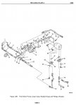
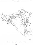
Here, the schematics for the dump and the wrecker are clearly labeled underneath:

wrecker pump.jpgdump pump.jpg

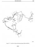
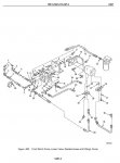
And the only other schematic that covers the linear valve and pump just generically says "Front winch pump, linear valve and related hoses"............ So which models does this work for? It's up to you to guess and find out!

Pump and piping cargo models.jpg

Anyway, the point of all of the above is you need to be an educated consumer. Make sure you know what you're buying and what you need.

Alright, on to the install-that's where the real misery is.

So, on any job, always do the most miserable part first. Since everyone knows M939 tranny PTOs are a nightmare, that's where I started.

Some folks say they just kept wiggling it until it fell into place. Their wiggle skills must far outweigh mine. The issue here is that the PTO is too close to the frame. They should have moved the powerpack over an inch or so or made a smaller PTO because the only way I was able to get the PTO installed was removing the left and right rear motor mounts, the right front motor mount bolt, the upper mount to radiator brace, the lower left front engine to radiator brace and the transmission mount (above the tailshaft). You do all this so you can pull the entire powerpack (engine/trans) over to the drivers side. I put a strap around the transmission tailshaft and ran a ratchet strap out above the framerail to a tree. I had to put a fair amount of arm into it to get it to move over far enough.

Below, you can see where we're going.

20160922_165841.jpg20160922_165835.jpg20160922_165851.jpg

Get your strap on.

20160926_112927.jpg20160926_112933.jpg

Removed motor mounts

20160926_112911.jpg20161030_173116.jpg20161030_180421.jpg20161030_180424.jpg


More in the next post. It'll take a few minutes, be patient.
 
Last edited:

HASSON1911

Member
748
24
18
Location
roseau/mn
I have been planning on adding to this thread for a while and since I'm sick and sidelined on the couch, today is it.

Since this thread is titled in a way that makes it always come up at the top for any M939 winch install, I think we're going to consider it the official "how to install a winch into an M939 series truck" thread and I'm going to add a bunch of stuff here that the OP didn't.

A friend of mine brought me this really clean M931A2 to add a winch to and convert to M932A2 specs. He had a complete takeoff winch kit from an M925 or M925A1. He had already installed the winch w/level winder. I did the rest. Up to this point, I had zero M939 winch knowledge, so I had to learn all of this.

I hope that before folks go out in to the world and buy takeoff winch kits, they read this thread. To be honest, it really makes me mad to see all these people, who are either not knowledgeable, or worse (and more likely), unscrupulous on eBay and all the Facebook pages for military vehicle sales selling kits and saying they fit all M939 models. Really makes me mad. Some poor guy is going to buy a kit that won't work for his model and is going to be halfway through the job before he realizes "oh crap, half my donor it is useless". It takes a lot of self restraint to not post on these people's ads "Hey, you say this fits all models, but it won't fit M932s, any M939A2 model, etc., etc.". The crappy nature of social media would probably just end up with me being flamed anyhoo.

So, the two things you really need to know is that these things are nothing like the older M39/M809 series 5 ton winches or the M44 deuce kits. On the older trucks, you can take a complete winch kit off a wrecker and put it on a dump, etc., etc. They're all the same. These (M939) trucks are not like this, for several reasons. The biggest issue is that the hydraulic tank mounts in a different place on almost every model. The cargo trucks mount on the passenger side, in between the middle tandem and the tool box. The tractors mount it on the drivers side, above the frame, right behind the cab. Dump trucks apparently use the reservoir for the dump hydraulics, which is under the bed, because I never found this model in the TM. Wreckers use the giant 80(?) gallon reservoir that hangs on the side of the hoist for the front winch. Weirdo models like the M934, I have no idea.

Dump (M930) reservoir:

View attachment 657283

Cargo (M925 and I think M928) reservoir:

View attachment 657284

Tractor (M932) mount:

View attachment 657285

And of course, the hydraulic tank itself is specific, since the brackets are welded on them. So it's now like you could just swap brackets. M925 shown on right, M932 shown on left.

View attachment 657286


Also, beware, on our M925 donor tank, it had a cracked ear from stress. Inspect carefully. I suspect ours isn't the only one out there like that.


Since the tanks go in so many different places, this means all the hoses and pipes are different and specific to your application. These can be very expensive.

The second issue is A2 versus M939/M939A1. The PTO, shift tower, PTO shift cable, PTO shift cable mounting bracket (bolts to the front of the PTO), PTO driveshaft are all A2 specific. The easiest way to identify the A2 PTO is that the upper center bolt is accessed from inside the PTO. The earlier model is an external bolt. The shift tower is A2 specific because of the different doghouse/firewall on an A2. The A2 tower is the one furthest away from the camera in the 2 shots below.

View attachment 657287View attachment 657288

The shifters themselves I believe to be the same from M939/M939A1 to M939A2 and I used the early shifters in our A2 tower, but the TM drawing is confusing here, because in the A2 schematic, they definitely look different. However, they're "greyed" out and the subsequent parts list doesn't even give a part # for them, so I had to assume they were the same as the pre-A2 shifters. See the difference:

View attachment 657303View attachment 657304

While I am discussing this, there are quite a few issues with the TM's regarding this job. A lack of proper identification is chief amongst them. There are multiple schematics that don't say what model they're for. For instance.....................................

Here, the schematics for the dump and the wrecker are clearly labeled underneath:

View attachment 657301View attachment 657300

And the only other schematic that covers the linear valve and pump just generically says "Front winch pump, linear valve and related hoses"............ So which models does this work for? It's up to you to guess and find out!

View attachment 657302

Anyway, the point of all of the above is you need to be an educated consumer. Make sure you know what you're buying and what you need.

Alright, on to the install-that's where the real misery is.

So, on any job, always do the most miserable part first. Since everyone knows M939 tranny PTOs are a nightmare, that's where I started.

Some folks say they just kept wiggling it until it fell into place. Their wiggle skills must far outweigh mine. The issue here is that the PTO is too close to the frame. They should have moved the powerpack over an inch or so or made a smaller PTO because the only way I was able to get the PTO installed was removing the left and right rear motormoounts, the right front motor mount bolt, the upper mount to radiator brace, the lower left front engine to radiator brace and the transmission mount (above the tailshaft). You do all this so you can pull the entire powerpack (engine/trans) over to the drivers side. I put a strap around the transmission tailshaft and ran a ratchet strap out above the framerail to a tree. I had to put a fair amount of arm into it to get it to move over far enough.

Below, you can see where we're going.

View attachment 657308View attachment 657307View attachment 657309

Get your strap on.

View attachment 657310View attachment 657311

Removed motor mounts

View attachment 657312View attachment 657313View attachment 657314View attachment 657315


More in the next post. It'll take a few minutes, be patient.
Sorry I dropped the ball, I ended up selling the truck and winch separate.

Glad you documented this to further help people!

Sent from my XT1254 using Tapatalk
 

clinto

Moderator, wonderful human being & practicing Deuc
Staff member
Administrator
Super Moderator
Steel Soldiers Supporter
Supporting Vendor
12,596
1,129
113
Location
Athens, Ga.
Ok, so in order to have room to get the PTO into place, you have to remove one of the tranny cooling lines on top of the trans, one that's behind the PTO (which has to come out in order to add the cooling line going to the PTO, the exhaust pipe and heat shield, etc. So with all that out of the way and the powerpack pulled over, make sure your PTO and transmission mating surfaces are clean. You need to shim the PTO to get the correct backlash. There is a spec in the TM and I don't remember what it is because I could not get my dial back indicator to fit anywhere that I could get an accurate reading. So you're back to the old "try a few gaskets and see how it feels" method, which is familiar to anyone who's added a PTO to an M44/G742 series truck. My experience with this truck was one .010" and one .020" gasket got me where I needed to be. Downside of this method is that you have to install the entire system, run it, see if it's noisy and if it is, remove the PTO again and re-shim it. And you have to know what feels or sounds wrong. If there's any way to use a dial back indicator and measure the lash, do it. If not, get an experience and professional friend who has done this a lot to feel it.

Clean surfaces:

20160926_112914.jpg20160922_165910.jpg20160922_165907.jpg

There's 2 ways (as far as I can tell) to get the PTO near the trans. You can feed it over the starter and move it back on top of the trans and try and pivot it down. That didn't work well for me. So I got it as tight inside the framerail behind the trans as I could, turned sideways and slid it up the frame until I got it near the opening and then rotated it in. This worked for me, your mileage may vary.

I used the factory weirdo bolt on top, which is a recessed allen head, studs on the top 2 side mounts, bolts on the bottom 2 side mounts and I think a stud on the bottom. Use thread sealer on them all and don't forget the copper sealing washers. Copper washer probably unnecessary on top inside one for obvious reasons.

20161029_153403.jpg20161029_153321.jpg20161029_153313.jpg20161029_153309.jpg


Cooling line: The PTO has a takeoff on the backside for a cooling line. The PTO in these is mounted in a place on the trans that won't get splashed enough. Don't forget this part. You'll need to remove your factory hose fitting and install one that has a 3rd port for the takeoff. See:

20161029_162623.jpg

Alright, with all that done, next, I'd hang the hydraulic tank. Since I'm working on a tractor, keep that in mind as you plan your mission.

Tractor tank has a small add-on support bracket that bolts to the outside of the drivers framerail.

20160921_103520.jpg

Do yourself a favor here kiddies, install the dammed drainplug in the tank now.

Ok, hanging the tank... oh wait, vendor shipped me a bunch of primed and bare metal stuff. Break out the paint!

20161030_131832.jpg20161030_163956.jpg20161030_182149.jpg20161030_184500.jpg

Now let's get our tank on.

20160921_131314.jpg20160921_131325.jpg531698_6006_353_0001.jpg <--- yeah, that's a GP pic. I forgot to take a good one. 20161101_174255.jpg20161101_174904.jpg

And here's some more fun stuff. On the tractor, the fluid exits the reservoir into a pipe and then hits a 90 degree elbow and heads down under the cab. The angle has to be perfect-too much down angle and the 90 fitting hits the tank frame, not enough and it hits the cab bottom. Real smart guys.

There are some various brackets that support the pipes. TM shows two, when I ordered the new tank, the frame didn't have any provisions for one of them. I talked to Memphis, they said they don't use them so I returned it.

20161101_174307.jpg

932 specific is this issue with the exhaust stack brace. Of course, the TM doesn't make it clear how this works on an M932. I kind of think the M932 is supposed to have a winch specific brace that is much shorter than the factory unit and instead of running all the way down to a bracket on the inside of the drivers frame, it goes to the reservoir brackets. But I didn't have an NSN for this so I was able to move the bracket towards the rear of the truck and re-use it. It's a tight fit, but I think serviceable (operational). Only question is what would happen if you flexed the heck out of the frame off-roading. Time will tell.

20161101_174324.jpg
 

clinto

Moderator, wonderful human being & practicing Deuc
Staff member
Administrator
Super Moderator
Steel Soldiers Supporter
Supporting Vendor
12,596
1,129
113
Location
Athens, Ga.
Alright, with the tank mounted and PTO in place, let's move the hydraulic pump and linear (diverter valve).

The way this system works is that you engage the PTO, the PTO spins a driveshaft that runs a hydraulic pump. Hyd. pump creates pressure and sends it to the linear valve, which you operate with the lever on the cab and it sends pressure to one of the two ports on the winch. One port is spooling in, the other is out.

Appears all models use the same pump, mounting bracket, shift cable and bracket.

20160221_162641.jpg20160221_162652.jpg20160221_162638.jpg20160221_162658.jpg20160221_162703.jpg

There will be some minor re-routing of electrical wires and air lines after the pump is installed. That's what those two clamps are for on the side of the bracket.

Use common sense here. There's driveshafts spinning and linkage shifting. Run your lines accordingly.

On to the hydraulic tank. Always check inside it. Look what I found.

20161109_122128.jpg

I'll be honest, this looks like this filter was over-pressured and it was the correct one. I crossed it in the -P. It's a Fram C-1666. I put another one in it and warned my friend to keep an eye on it. I don't think this is water freezing damage.

Ok, not as bad as the PTO but still some pretty crappy design work. First, the easiest way and maybe only way to install this is to take the filter head and can off the bracket but leave the 2 bolts in it, because once the bracket is bolted to the frame, it's too close to the tractor deck to get the bolts in. Other models may be different. So clean it and install it like so:

20161109_132628.jpg20161109_134955.jpg

Before and after. EVERYTHING HAS TO BE CLEAN, ARRGGHHH THE OCD IS KILLING ME.

20161109_122134.jpg20161109_135824.jpg

Once the filter head is installed, install the filter and can and you're ready to move on to the next part.

Ok, we've got the linear valve, pump, PTO and reservoir and filter in place. Let's get a driveshaft in place.

Like I said, A2 driveshafts are specific, they're longer. So, I had to have ours lengthened at the local driveshaft shop. Luckily, they left it bare metal so it could instantly rust so I had to prep and paint it. Thanks! I believe the A2 driveshaft is 12.625" longer than the early one but MEASURE YOUR TRUCK YOURSELF!!

20161103_143341.jpg20161103_150955.jpg

The driveshaft will install on both shafts by compressing and then sliding back out and there are 3/8x16" bolts that thread into each yoke to keep anything from coming loose. I had to rearrange the clamps for our slave cable to clear the driveshaft. I wouldn't be surprised if factory winch trucks have a different slave cable retention bracket. The picture below shows how the factory routed them. I flipped the clamp 180 degrees so the cables were held closer to the framerail.

20161102_152633.jpg

Alright, now with the pump, valve, reservoir and driveshaft installed, we can start hanging hoses. Inspect any used hoses you plan on using carefully.

20161103_154858.jpg20161103_154841.jpg20161103_154901.jpg

More in next post........................
 

Attachments

Last edited:

clinto

Moderator, wonderful human being & practicing Deuc
Staff member
Administrator
Super Moderator
Steel Soldiers Supporter
Supporting Vendor
12,596
1,129
113
Location
Athens, Ga.
Alright, as I was saying, this stuff is big. So you may have to be clever in order to get it installed.

20161102_105612.jpg20161102_105606.jpg20161102_105618_001.jpg

This feed hose is big and it's designed to flex in order to get it in place. Improvisation.

Again, everything is specific. This pump came off a cargo truck. Note the rear hose fitting. For a tractor, it's removed and the tractor specific hose clamps directly to the pump. See below.

20160221_162638.jpg

Ok, on to the install:

20161102_095738.jpg20161102_100734.jpg20161102_102808.jpg

I didn't get pictures of all the hose installation, but I think almost all of the hoses are model specific except the winch to linear valve hoses and the pump output to linear valve hose and pipe. Maybe the return hose that comes back from the linear valve to the hydraulic filter is the same. The filter is on the low pressure return side of the system.

Ok, so with most of the stuff on the bottom buttoned up, it's time to move topside.

I forgot one thing though............... Once I had installed the PTO, I had to move the strap and pull the powerpack back into position....... and I got everything to line up except the right rear motor mounts......... I tried everything and finally gave up and jacked up the right rear corner of the engine, loosened the motor mount brackets, got the bolts to line up and start threading, then had to let it all back down. Thanks again engineers, for your seething hatred of the poor, pitiless souls who have to service your rotten ideas.

20161105_143247.jpg20161105_143252.jpg

Alright, on to the shift tower.

Let me tell you, the easiest way to do this is to assemble the tower on the work bench, with both of the shifters and the cables routed through their clamps, then knock the pre-punched holes out of the floor insulation and cab, then feed the cables down through the floor. Because the winch control cable has to snake a pretty strong angle to get from it's clamp in the tower to the hole in the floor and it's a thick cable........ hard to flex.

Pics:

20160217_140206.jpg20160221_162604.jpg20151227_133830.jpg

Look at the cable that is on the left......... it comes out of the firewall and goes back at a pretty severe angle, going over the PTO. This is the winch control cable and this is the only way it will work.

20161108_164726.jpg20161108_140236.jpg20161108_172125.jpg

It took me a fair amount of time to get these adjusted properly. The PTO I had a friend there to help me with. He'd shift it, I'd check and see how far it engaged and adjust accordingly. The winch control I didn't have time to adjust, I'm going to fine tune it the next time I get the truck.

Ok, the clevis on the left is what goes from the PTO shift cable to the arm on the PTO. Gap is way off, I got a bushing from the local hardware store and it is perfect and shifts really well. Note positioning of cables, brackets, etc.

20161108_110153.jpg20161112_140826.jpg20161112_141020.jpg20161112_141025.jpg20161112_141030.jpg
 

clinto

Moderator, wonderful human being & practicing Deuc
Staff member
Administrator
Super Moderator
Steel Soldiers Supporter
Supporting Vendor
12,596
1,129
113
Location
Athens, Ga.
This is what I meant about the clevis and shift arm:

20161111_163835.jpg

Ok, so now, the system is complete and you've filled it with fluid. I used Napa AW32 10W. 932 took 8 gallons.

So, this last part covers the way the wire rope rolls onto the drum.

EDIT: I originally thought level wind equipped drums had their rope rolled on backwards from non level wind applications, but I was apparently incorrect. Someone had simply rolled the rope on this truck's drum wrong.

As you can see, this would have been a problem. Glad I caught it!

20161109_161114.jpg20161109_161123.jpg20161109_161126.jpg20161109_161145.jpg

Once I unrolled the cable, I took the hold plug out of the drum and inserted the cable the right way. Again, improvisation is key. Not enough driveway? Snatch block. Leave it there for weeks and watch people just look at and wonder "what's this idiot doing now?"

20161113_165636.jpg20161113_165644.jpg20161113_165700.jpg20161113_170325.jpg

Trying to roll it back is where I learned all about level winders. rofl

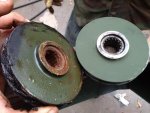
So, unfortunately, the vast majority of us have to leave our trucks outside and even if we're the privileged few, it doesn't help that they were outdoors for the 20-50 years before we bought them. What I found on this level winder was that all the rollers were seized up from not being greased and moisture getting in. So, take everything apart and get the rust out! woo hoo!

IMG_7871.jpgIMG_7870.jpgIMG_7869.jpgIMG_7868.jpgIMG_7872.jpg

The tensioner pulleys have Torrington bearings in them. I was impressed.

Clean everything up in the trusty old parts washer. Love mineral spirits. Yes, the pictures are a little out of sequence. Deal with it.

IMG_7874.jpg


Now, the tensioner pulleys work and the tensioner level works. And, the spindle pulley is frozen-won't rotate or spin.

Grease the heck out of it, look what comes out:

IMG_7877.jpgIMG_7876.jpg

I was running out of time to do this the right way, if I'd gotten this project done sooner, I'd have taken this apart and cleaned it properly and put it back together. Instead, I pumped a ton of grease in it and put a 3' prybar in it and forced it to behave.

And finally............... this happened:

IMG_7878.jpgIMG_7879.jpg
 
Last edited:

86m1028

Active member
1,687
17
38
Location
Murphy TEXAS
Sorry, I didn't take pics. They are the 2 rear most bolts on both frame extensions. I just made a simple template off of the extensions referenced from the two bolts that hold the cross member for the hood. I drilled the holes(1/2 inch) and when the extensions were in I just ran the drill in them again to finalize the lining up of the holes. I also mounted the entire assy as one piece. The winch, frame extensions, and bumper was all assembled as one. I also used a tow truck boom to single point lift the assy and that allowed us to manhandle/maneuver the assy into the frame. I think that worked a little easier than a forklift.
Out of curiosity, was it a am general or bmy ?
I think all the bmy trucks have the holes.
I did not have to drill any holes in the bmy truck I converted.
 

clinto

Moderator, wonderful human being & practicing Deuc
Staff member
Administrator
Super Moderator
Steel Soldiers Supporter
Supporting Vendor
12,596
1,129
113
Location
Athens, Ga.
Oh wait, there's one more thing.......................... rofl

How many of you guys have ever replaced the electroline fitting on a winch?

The manufacturer says it works like this:

http://www.esmet.com/electroline-end-fittings-swivels.html

Look at the flash animation that's halfway down the page that I'm not smart enough to capture and post here so in 6 months when the manufacturer changes their website, we'll never see it again.

They make it look really easy. It's not.

20160221_164202.jpg20160221_164155.jpg20160221_164150.jpg

Esmet will send you a bare metal part. It will get rusty before you can install it. You will install it in your glass bead cabinet and make it pretty again and then epoxy prime it and paint it so it will have a chance of retaining some paint after it gets used.

20161109_155413.jpg20161109_161017.jpg20161109_161019.jpg20161109_161026.jpg20161109_161105.jpg

I'm still not 100% sure I did this right.


IMG_7880.jpg

I don't have any pictures of the finished project because it's dark and we were all busy. But the problem is that the 6 wire bundles need to lay in the grooves of the bronze fitting and they do not, in any way, want to do that. The fiber core of the rope goes through the center and you should be able to see it through a sight hole on the main body. This is how you know the connection is working or failing....... if the fiber core starts to move or disappear, you know you're pulling the rope out of the connection and it's failing.

ok folks, I hope this helps ya'll in your M939 winch installations.
 

Attachments

clinto

Moderator, wonderful human being & practicing Deuc
Staff member
Administrator
Super Moderator
Steel Soldiers Supporter
Supporting Vendor
12,596
1,129
113
Location
Athens, Ga.
Sorry I dropped the ball, I ended up selling the truck and winch separate.

Glad you documented this to further help people!
Oh man, I didn't mean it that way. If you sell something, nobody can blame you for not posting up how the project finished!

As I was doing this job, I repeatedly thought of this thread and thought "Hasson probably set the truck on fire and that's why he never finished that thread".
 

Castle Bravo

Hundredaire Socialite
Steel Soldiers Supporter
1,964
215
63
Location
Arizona
I applaud the information contained within this thread and appreciate the time it takes to gather such knowledge.

I haven't looked through everything here yet, but I can say this as a "correction" -

The M932 hydraulic reservoir is located between the passenger side fuel tank and the quarter fender. Somewhere, I have a photo, but I'm not able to find it right now. I don't know if it sits on the same bracket as the cargo trucks or is different. The M932A1 and M932A2 have it behind the cab as pictured above.

I'm also thinking that the level wind doesn't change the way the cable is spooled - it is over the top of the drum whether or not it has a level wind.
 

Swamp Donkey

The Engineer
Steel Soldiers Supporter
1,450
119
63
Location
Gray, GA
Excellent writeup Clinto!

I'll add a link to the thread below in here as it deals with the frame extensions and way too much research into them. It also explains the holes in the rear of the inner rails and the difference between the hood trunnion crossmember between the frame rails for W/W and WO/W trucks.

http://www.steelsoldiers.com/showthread.php?135158-M939-Frame-Extensions

Keep in mind that the outer rail holes are completely symetrical, so they can be used on either side. There is a left and right for the inner rails though, which is detailed in the thread. Every frame I've seen from A0s to A2s has the holes already in the frame. The only time holes will need to be drilled "should" be if you're trying to use two of the same side inner rails. I have not seen every single truck though. Exceptions might be the rule.
 
355
12
18
Location
New Enterprise Pa
I just did this install also on a BMY 931A2. I went about the hoses and controls a different way. I didn't like how low the hoses were under the truck so I made my own plumbing. and I used off the shelf cables and made a lever setup of my own. I'll take some pics and post. My pto was for a A1 truck but it still worked. to get it in I had a bottle jack between the frame rail and the back of the trans and gently pushed it over some to install the pto. but I also had to notch the frame a little more to be able to clear the pto lever but t wasn't much.
 
Top