Ronmar
Well-known member
- 4,148
- 7,961
- 113
- Location
- Port angeles wa
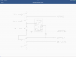
Was asked to start a separate discussion and a manual ctis drawing. we already had a thread on it so I revived that with a current diagram. it is also in my videos on youtube linked in this discussion.
basically pin H is 24v. Pin R is control, pin B is inflate and pin C is deflate. You energize control to seal the system, and give a shot of inflate to pressurize the system and open the wheel valves… then you can continue to inflate or deflate. Opening control releases system pressure closing the wheel valves in a normal working system… You of course need a pressure gauge connected to the PCU pressure sensor port to measure tire pressure when the wheel valves are open…

basically pin H is 24v. Pin R is control, pin B is inflate and pin C is deflate. You energize control to seal the system, and give a shot of inflate to pressurize the system and open the wheel valves… then you can continue to inflate or deflate. Opening control releases system pressure closing the wheel valves in a normal working system… You of course need a pressure gauge connected to the PCU pressure sensor port to measure tire pressure when the wheel valves are open…


