• Steel Soldiers now has a few new forums, read more about it at: New Munitions Forums!

  • Microsoft MSN, Live, Hotmail, Outlook email users may not be receiving emails. We are working to resolve this issue. Please add support@steelsoldiers.com to your trusted contacts.

MEP 002A Glow plugs

bmwsyc

Member
80
0
6
Location
Brooklyn Center, MN
I was wondering if anyone new a source for new glow plugs for the MEP's I did a search here and found a 2006 posting that said that Champion CH42 plugs are correct, but Champion's website says that they are discontinued without a replacement. Any ideas? I'd rather get new ones from a commercial source. I'd rather not but used plugs.
 

bmwsyc

Member
80
0
6
Location
Brooklyn Center, MN

doghead

4 Star General /Moderator
Staff member
Super Moderator
Steel Soldiers Supporter
26,246
1,177
113
Location
NY
I just looked through the TM 9-6115-584-24P. I don't know of nor could I find any glow plugs in the block. Please tell us what figure and part number from the TM, are you referring to.
 

319

Lieutenant
Steel Soldiers Supporter
3,350
58
48
Location
Michigan
I just looked through the TM 9-6115-584-24P. I don't know of nor could I find any glow plugs in the block. Please tell us what figure and part number from the TM, are you referring to.

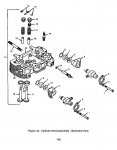
Figure 44, page 149, item #9 NSN 2920-01-048-8867
 

doghead

4 Star General /Moderator
Staff member
Super Moderator
Steel Soldiers Supporter
26,246
1,177
113
Location
NY
Ah, it's in the head, not the block.
 

Attachments

bmwsyc

Member
80
0
6
Location
Brooklyn Center, MN
Plugs replaced today, starts much easier now. Was able to replace the plugs without taking anything else apart. Probably the hardest part was getting my hand in to reconnect the electrical terminals...didn't want to run down to the basement to get a needlenose.
 

treeguy

New member
605
3
0
Location
Fort One Bay - Cape Cod, MA
I know that this is an older thread but I'm trying to follow up on a coment made by another member. I wanted to put this here in this thread and not clutter someone elses discussion where this originated.

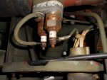
This is in regard to the manifold heater wiring. The attached pic. is how my OO2' came to me and after reviewing the TM's the wiring to the heaters looks correct. To me this looks wierd, the heating element on the left does not look like it could ever do anything because the terminal post is wired to the manifold body which will ground it. So that is why I thought that it might be a spare all ready to go, just move the hot wire from the other heater to it.

If the two heating elements are supposed to be wired in series how does that work concidering my picture. A ground is a ground is a ground, so the heating element looks dormant to me. Any thoughts?
 

Attachments

Speddmon

Blind squirrel rehabiltator
Super Moderator
Steel Soldiers Supporter
4,640
28
38
Location
Cambridge, Ohio
I'll have to look at mine when I get home, but from what I can see in the TM's that is correct, although it does look goofy. The -24 TM shows the manifold heaters and mounting breakdown. And in that picture, it appears that the wire in question does indeed go to the ground.

I'll look at mine when I get home tonight and let you know.
 

Speddmon

Blind squirrel rehabiltator
Super Moderator
Steel Soldiers Supporter
4,640
28
38
Location
Cambridge, Ohio
I looked at one of my spare engines tonight when I got home, and the picture you posted is indeed the correct way to wire the manifold heaters. I think why it is confusing is because the block they are mounted to is isolated from the manifold, so the 24 volts enters the bottom of the first element at the stud and passes through to the second element via the block they are mounted in, and then from the stud on the bottom of the second one to ground via the bolt. Remember, these are a resistive heating element, so the power cares not which way it goes through the element, as long as it goes through.
 

treeguy

New member
605
3
0
Location
Fort One Bay - Cape Cod, MA
I hear what your saying but I don't see how that could work. Power goes in to one, insulated from ground, into the heating element and then to ground via the threaded body. If there was power from the first heater transfered to the second thru the block than the block would have live 24v and there would be NO ground or a short because the block is grounded to the manifold by-passing the gasket with the two mounting bolts. I visualize this like a regular spark plug, power in - body ground, there is no available power on the threaded body so how does power transfer to the other manifold heater? It looks like one of lifes great mysteries. That is why I said before that it may be a spare and you just move the wire over if you needed it. Wouldn't it be easier for a young troop to visualize this in the field if the two heaters were just jumped together from terminal to terminal. That is how I thought it should have been wired, hence this post. Thanks for your ever present knowledge on these things Speddmon!

ps. Have you heard if Joesco or Luckydog have had any progress?
 

PeterD

New member
622
6
0
Location
Jaffrey, NH
I hear what your saying but I don't see how that could work. Power goes in to one, insulated from ground, into the heating element and then to ground via the threaded body.
I think you missed the fact that the block they screw into is not grounded, but is isolated (electrically) from ground. Power goes into the first heater, through the block to the second heater, and from the second heater to a ground wire to the bolt (which is insulated from the block) which attaches the assembly to the intake.
If there was power from the first heater transfered to the second thru the block than the block would have live 24v and there would be NO ground or a short because the block is grounded to the manifold by-passing the gasket with the two mounting bolts....

ps. Have you heard if Joesco or Luckydog have had any progress?

The bolts have insulation on them...
 

treeguy

New member
605
3
0
Location
Fort One Bay - Cape Cod, MA
OK, I see the insulation on the bolts. So the block is electricly isolated from ground and the heaters both get power, just the second one in reverse than the first. OK got it, but does that mean that when the heaters are activated the block is energized with 24 volts. That is the only way this would work, right? And..... how is the first heater grounded (the one on the right) it just has power in and then out to the second one? Power is useless or unusable unless it flows thru to a ground to complete the loop, right? :cookoo:
 

PeterD

New member
622
6
0
Location
Jaffrey, NH
OK, I see the insulation on the bolts. So the block is electricly isolated from ground and the heaters both get power, just the second one in reverse than the first. OK got it, but does that mean that when the heaters are activated the block is energized with 24 volts.
No, the block will have about 12 volts, or half the battery voltage.
That is the only way this would work, right? And..... how is the first heater grounded (the one on the right) it just has power in and then out to the second one? Power is useless or unusable unless it flows thru to a ground to complete the loop, right? :cookoo:
Power to these heaters goes like this. The power in wire (on the right hand one in the above image) which flows through the first heater. Then it flows through the threaded part on the base to the second heater's base. If flows through the second heater, to the wire on the top of it (left wire) which grounds under the mounting bolt.

So the block is at half battery voltage, one heater, the block then the other heater.
 

Speddmon

Blind squirrel rehabiltator
Super Moderator
Steel Soldiers Supporter
4,640
28
38
Location
Cambridge, Ohio
OK got it, but does that mean that when the heaters are activated the block is energized with 24 volts. That is the only way this would work, right? And..... how is the first heater grounded (the one on the right) it just has power in and then out to the second one? Power is useless or unusable unless it flows thru to a ground to complete the loop, right? :cookoo:

The first heater is grounded, but it has to go through the second element to get to ground. Since they are wired in series, if either element burns out, they both stop working since you no longer have a complete path through either one to ground. You're not thinking about the voltage drop across the heaters. Since the heater elements are exactly the same, each one drops 12 volts across it...so, you feed 24 volts to the first one...It uses 12 of those volts and leaves 12 volts at the block to feed the second element (in reverse). The second element uses the other 12 volts.
 
Top