• Steel Soldiers now has a few new forums, read more about it at: New Munitions Forums!

  • Microsoft MSN, Live, Hotmail, Outlook email users may not be receiving emails. We are working to resolve this issue. Please add support@steelsoldiers.com to your trusted contacts.

MEP 002a Not producing Electricity, I am looking for someone who is familiar with the 002a to work on it.

chb32nj

Member
31
42
18
Location
Chatsworth, NJ
OK, lets agree that 13-15 test are good to go.
Then test 10-12 should be good.

Test 1-3. You should get no continuity, between T1 and T2, or T2 and T3, or T1 and T3. They are not a pair. So they should be open. Those tests should be GOOD.

That leaves test 4-9. Here I see a problem,


These are the wire pairs, for the phases. T2 to T5 is NOT a good reading. I seem to remember that its a PITA to take these readings, and I had to do it several times to make sure I had the right pins. I would do this again, to be sure.

The J12 plug test is also good.


When I did these tests back about a million years ago. We used a Wheatstone Bridge. Is a Multimeter made to todays standards, as good as a wheatstone bridge? I also thing the readings are to be taken at 25 degrees CELCIUS.
The J 12 Plug test was on start up holding the S1 on for 30-45 seconds (I knew there was something else I forgot to post in the notes). P9 and P10 are references to the plugs that go into J9 and J10 as you stated Guyfang. To sum up tests 10-15, every pin on both plugs were open circuit except for P10 Pin A which was 000 with the negative lead to Ground and the Stator housing. I hope this clears up any confusion by the chart I posted. Thank you for your help.
 

Guyfang

Moderator
Staff member
Moderator
16,777
24,105
113
Location
Burgkunstadt, Germany
The J 12 Plug test was on start up holding the S1 on for 30-45 seconds (I knew there was something else I forgot to post in the notes). P9 and P10 are references to the plugs that go into J9 and J10 as you stated Guyfang. To sum up tests 10-15, every pin on both plugs were open circuit except for P10 Pin A which was 000 with the negative lead to Ground and the Stator housing. I hope this clears up any confusion by the chart I posted. Thank you for your help.
Not your fault. The books are sometimes wrong, or written strange.


Unscrew J12. Mesure the restince of the two wires that go into the gen head. You should get continuity. Look at the snip of the wire diagram. The F1 and F2 wires inside the gen head are simply to a coil that lights the gen head off on start. Tell us what you get. Open or continuity.
 

chb32nj

Member
31
42
18
Location
Chatsworth, NJ
Correct me if I am wrong but if it had shorted on ALL of the windings then it would have let out a LOT of magic smoke and it would certainly smell like it did.
If that happened it was at Robins AFB in GA. That is where I got both MEP-002a's from. It never gave a whif of smoke since I owned it. I did not smell anything residual when I did the diode test. In my opinion FWIW, I think someone at Robins was working on this because I feel the Stator is new. The wires have no green paint on them (all the other wires on the gen have been painted over) and they are not the least bit dry rotted or stiff. The plugs are like new with not one burr mark from channel locks. The big question is did this Gen set go thru a complete overhaul and something was put back together incorrectly or did they just try to fix the problem at hand by replacing the stator. The Gen had .5 hours on it at time of auction and the engine runs great. I personally think it was overhauled because the circuit boards and wiring inside of the control box looks like it is brand new. Just my opinion.
 

Ray70

Well-known member
2,595
5,914
113
Location
West greenwich/RI
In addition to Guy's suggestion of measuring F1 and F2, Maybe a recheck of the 6 winding pairs is also in order. The Wheatstone and Kelvin bridge are probably more accurate than a DMM but I've measured them before using a standard DMM and the readings were fairly close. Definitely not Zero ohms.
Zero ohms on all 6 windings would definitely be a problem, if they really are zero ohms.
 

chb32nj

Member
31
42
18
Location
Chatsworth, NJ
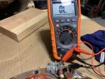
I rechecked all the circuits on the winding resistance test as Ray70 suggested. This time with a brand new DMM. I researched the Wheatstone Bridge and that is not going to happen. I did read about how a cheap DMM will not give extremely accurate readings in some test modes. My cheap DMM fit that bill perfectly. I bought the best Klein DMM that HD had. It has an auto-ranging measurement mode . This automatically determines the most appropriate measurement range for the testing that is being conducted. Needless to say the readings are completely different. All the open circuits stayed the same but I have actual number values for the others. I have updated the chart with the 2 tests side by side for comparison which I am attaching. With these new test numbers maybe the coil Guy referenced in his last post is the problem. I don't know where it is located. If it is located near the diodes I will try and check it tomorrow. Thanks everyone!


1/10/2021-This is an edit to make a correction to the chart. See post #74 for an updated chart. Here is the correction; Test #5 is T2 & T5 which is P9D and P10F. When I wrote down all the crossovers from wire to plug position I made a mistake for T5 and listed it as P9F instead of P10F. Sorry for any confusion.
 

Attachments

Last edited:

Ray70

Well-known member
2,595
5,914
113
Location
West greenwich/RI
Well, hopefully Guy will check the new readings tomorrow, but right off the bat, the F1 to F2 resistance looks like a problem. Those are your Field excite wires which if there is an open circuit , there is no way the regulator can excite the field to create any power.
 

rickf

Well-known member
Steel Soldiers Supporter
3,146
1,684
113
Location
Pemberton, N.J.
Getting closer! I am an electrical guy and I have to say you guys are making my head hurt! Good work from all involved.
 

Guyfang

Moderator
Staff member
Moderator
16,777
24,105
113
Location
Burgkunstadt, Germany
Well, hopefully Guy will check the new readings tomorrow, but right off the bat, the F1 to F2 resistance looks like a problem. Those are your Field excite wires which if there is an open circuit , there is no way the regulator can excite the field to create any power.
Indeed. This is a no go. The two wires go to a coil inside the Gen head, (in army talk, Main Gen) to light off (excite) the main gen. An open indicates a break someplace in the circuit.

Test #5, is a no go. T2 & T5 are a pair. They go to a coil in the main gen. An open indicates a break someplace in the circuit.

Not good. But don't jump from the bridge with your pockets full of rocks yet. Take the plugs apart. look for loose or broken wires. Normally when a wire BREAKS, its within 5-7 cm of the ends of the wire/cable. An old trick is to run the wire between your hands, or better yet, fingers. Back and forth. If there is a break, you can often FEEL it.

Failing that, you can open up the main gen. take it out. Put it on a CLEAN table and start opening it up. Look for loose wires, and broken/burnt wires. Trace your problem wires to the source.

If you find nothing, you have two options. Rewind the thing, and I can not tell you what that cost in the States. Maybe Ray can. Or, simply find another main gen.

If you go for a rewind, ask around. Ask around for peoples opinion about the shop. Ask the shop if they want to pull the stator coil pack or if you have to. Its not hard, but you got to be earful. Best is if they do it, because if they screw it up putting it back in, they have to fix it. Like I said, not hard to remove. You basically need a flame thrower and a nice hammer.
 

rickf

Well-known member
Steel Soldiers Supporter
3,146
1,684
113
Location
Pemberton, N.J.
"Like I said, not hard to remove. You basically need a flame thrower and a nice hammer."

I love it. :LOL: But he said the stator was replaced already so that would tell me to look at the wires on the plug. It may have just been a bad plug all along? I seems to me that this set had an issue that they tried to fix and when they couldn't it went out for auction. So I would eliminate the parts that were replaced and concentrate on what is left that is testing bad. You guys are so far ahead of me now I have no idea what tests are what but are any of those tests covering stuff that was not replaced in the repair?
 

Guyfang

Moderator
Staff member
Moderator
16,777
24,105
113
Location
Burgkunstadt, Germany
"Like I said, not hard to remove. You basically need a flame thrower and a nice hammer."

I love it. :LOL: But he said the stator was replaced already (No. The main gen, and the stator is a part of it, have not been changed. I just read this whole thread, 3 times) so that would tell me to look at the wires on the plug. It may have just been a bad plug all along? I seems to me that this set had an issue that they tried to fix and when they couldn't it went out for auction. So I would eliminate the parts that were replaced and concentrate on what is left that is testing bad. (all the parts concerning this system have been changed, BUT, the Main gen. So, the problem HAS to be in the main gen, or cables leading to the main gen. By testing, we have isolated the F1 and F2 as being a problem, and T2 and T5 pair, as being a problem. Hence, the wires leading to these three things, and farther on, into the system have to be our problem area. You guys are so far ahead of me now I have no idea what tests are what (I do not always recall this stuff, so I read the whole post over, and over) but are any of those tests covering stuff that was not replaced in the repair?
 

chb32nj

Member
31
42
18
Location
Chatsworth, NJ
Thank you Guy for the help and advice. I checked the plugs tonight and they are all good. I will start taking the Generator apart this weekend. Hopefully the problem is at the other end of the J12 plug for F1 & F2. I have to take it off now anyway, whether I find the problem or I replace it with another Gen End. I apologize for any confusion or headaches from the chart I made. For me it was the best way to record the results of exactly what I tested and share them on this thread so everyone could see exactly what I did.
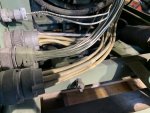
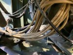
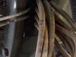
And Rickf, my comment about the stator was my opinion only which I stated more than once. I just want to be clear I have absolutely zero knowledge about anything done to this 002a before I bought it. The auction at Robins AFB probably had 30 generators, 5-8 of them being 002a's. The comment I made about the stator was from my observation of its wires and plugs and comparing it to my other 002a. I am posting 3 pictures of the wire harness for the stator. Thanks everyone for the help and I will post when I get it apart.
Guyfang, btw, no need for a flame thrower and a hammer. I have a Cat mini excavator. With a flick of my wrist I guarantee it will be separated!! LOL!! Army Green is tough but nothing beats Caterpillar Yellow!! Just wanted to end on a light note. :)
 

Attachments

Last edited:

Guyfang

Moderator
Staff member
Moderator
16,777
24,105
113
Location
Burgkunstadt, Germany
The cat is good, but still, you need the flamethrower. I once pulled a stator out of a 3 foot in diameter underwater pump, while at a FLYGT underwater pump school. We heated up the housing, and then raised the housing about 3 inches above a pad of cardboard. The dropped it. It slid out like it was buttered. Put it back in the same way. When the housing cooled off, you would have thought it was cemented in.
 

rickf

Well-known member
Steel Soldiers Supporter
3,146
1,684
113
Location
Pemberton, N.J.
As much as I love military generators, at that point I am going to Harbor Freight for a Chinese special! Power goes out around me quite often and say what you will but several of my neighbors have those Chinese sets and they just run and run, 24 hours a day. And like they tell me, for what they paid for them when it does finally die they will just buy another and still be way ahead of the game compared to buying a military set nowadays.
 

Ray70

Well-known member
2,595
5,914
113
Location
West greenwich/RI
Agreed... Those Chinese gens just run and run... 24/7 for a couple days on end.... then die in the middle of the outage rofl
Then, once the power comes back and the stores reopen and restock, you buy another and repeat! :doh:
But, yes... cheaper than Green Iron!
Just kidding, everyone has their opinion and buying multiple cheap machines is a fairly common plan, and it works for some.
 

chb32nj

Member
31
42
18
Location
Chatsworth, NJ
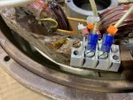
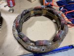
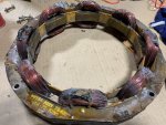
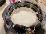
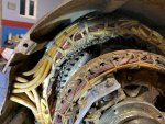
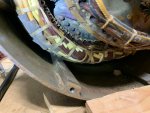
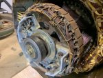
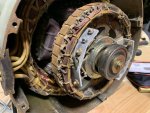
I pulled the Gen Head today and was able to get it apart. The Gen Head separated from the engine without too much trouble or persuasion. Separating the End Bell from the bearing was more difficult. I unbolted the exciter stator and looked for burnt or broken wires, nothing. I tested F1 & F2 for resistance on the terminal block, open circuit. I disconnected the wires from the terminal block and tested for resistance, nothing. I kept one test lead on the F1 wire and gently tried get continuity by touching the other test lead to all the connecting wires between the coils, nothing. I then put the test lead on F2 and did the same thing, nothing. The copper windings have a coating on them so that could be why I don't get any readings. I examined the exciter stator closely for a broken or burnt wire. I could not find anything broken or burnt. I am going to attach a few pictures.
 

Attachments

Guyfang

Moderator
Staff member
Moderator
16,777
24,105
113
Location
Burgkunstadt, Germany
When you checked the diodes, did you unsolder them? Remove them from the diode bridge? Also, you should be able to test for continuity from F1 and F2, to the input sides of the diodes, I think. I never did it, as it was wasted time for me. I simply put another exciter rotor or stater on. No need to test. But you should be able to check that.
 

chb32nj

Member
31
42
18
Location
Chatsworth, NJ
I did not unsolder the diodes but I did remove them from the bridge. I let them hang not touching anything and attached the alligator clips to it. I did not check anything on the stator rotor side. I got it apart and concentrated on the exciter stator looking for any broken wires and checking continuity. I will check the F1 & F2 input sides of the diodes and also take a look at the T2 & T5 that was mentioned in an earlier post.
A couple of questions for you Guyfang, do I need to unsolder the diodes even if they are disconnected from the bridge to test them accurately? They tested ok once they were disconnected from the bridge. What is your opinion of img 6764, testing the exciter stator? In your past experiences with exciter stators going bad, can you usually see the problem or is it hidden like a possible broken wire inside one of the windings? I googled the exciter by name, description, & part numbers and found nothing available. Thanks for your help!
 

Ray70

Well-known member
2,595
5,914
113
Location
West greenwich/RI
Hi Chris, When you tested the exciter stator you got an open circuit at the terminal block. You got the same result when you disconnected the wires and retested. You will not get any readings by trying to probe the coils because of the coating on the wires.
Maybe try back probing the ring terminals on the exciter stator wires to check for a bad crimp and look where the terminal wires join the windings to see if you can find a break somewhere. Other than that for it to have an open circuit you must have a break hidden somewhere within one of the coils.
 

Guyfang

Moderator
Staff member
Moderator
16,777
24,105
113
Location
Burgkunstadt, Germany
Chris,

My mentor told me to ALWAYS unsolder the wire. To NEVER take more then one diode out of the bridge at a time, to preclude screwing it up on reassembly. So thats the way I did it, every time. But it F1 and F2 are open, and T2 and T5 are open, that is where you need to look first. Ray hit it right on the head. If a coil is open, that can be fixed at a shop.
 
Top