• Steel Soldiers now has a few new forums, read more about it at: New Munitions Forums!

  • Microsoft MSN, Live, Hotmail, Outlook email users may not be receiving emails. We are working to resolve this issue. Please add support@steelsoldiers.com to your trusted contacts.

MEP-003 Water in Exhaust

Ray70

Well-known member
Steel Soldiers Supporter
2,634
6,060
113
Location
West greenwich/RI
Agreed, you are in good shape to get this done.
So follow the procedure in the TM. Seeing that you will have the valve covers off, rotate motor clockwise until the #1 intake valve closes ( 2nd valve from the right ) continue rotating clockwise about another 90* or so until the "PC" mark is directly aligned with the pointer in the bellhousing hole.
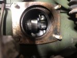
Now, as a 2nd verification step ( or for anyone else doing this and doesn't have the valve cover off, in the attached picture you will see the IP cam lobe just left of center , to the right of the gear in the IP mounting hole. The cam lobe to it's right is #1 intake. The cam rotates COUNTERCLOCKWISE , so in the attached picture you can see that the cam has passed by the lifter and is now pointing towards the opening and down on like a 30* angle. This motor is currently positioned at "PC" on #1 , ready to install the pump.
Now, with that said, this is a tip to verify your work.... knowing the procedure per the TM is Key to understanding how things work, tips are to help verify you understand the procedure and what is happening mechanically inside the engine (y)Cam lobe.JPG
 

GAPRIME

Member
41
26
18
Location
GA
Thanks Ray,

Worked on this last night. The code inside the bellhousing is "B" - is that correct or should I continue rotating looking for "PC". From the TM they are not clear about this but they have a Table 7.1 with different letters...


Agreed, you are in good shape to get this done.
So follow the procedure in the TM. Seeing that you will have the valve covers off, rotate motor clockwise until the #1 intake valve closes ( 2nd valve from the right ) continue rotating clockwise about another 90* or so until the "PC" mark is directly aligned with the pointer in the bellhousing hole.
Now, as a 2nd verification step ( or for anyone else doing this and doesn't have the valve cover off, in the attached picture you will see the IP cam lobe just left of center , to the right of the gear in the IP mounting hole. The cam lobe to it's right is #1 intake. The cam rotates COUNTERCLOCKWISE , so in the attached picture you can see that the cam has passed by the lifter and is now pointing towards the opening and down on like a 30* angle. This motor is currently positioned at "PC" on #1 , ready to install the pump.
Now, with that said, this is a tip to verify your work.... knowing the procedure per the TM is Key to understanding how things work, tips are to help verify you understand the procedure and what is happening mechanically inside the engine (y)View attachment 859120
 

GAPRIME

Member
41
26
18
Location
GA
Also the gear on the pump is rotating but you need some amount of pressure to move it - is this normal? Not sure what you meant by "freely".

Trying to avoid opening the IP if possible...


Just spin the gear, make sure it turns freely now. then push in on the cap where it rides against the cam, it should move in and out freely ( the spring force is tight but you an press it with your thumb )
You could also take out the delivery valve so you can see the plunger movement in and out, if you have any doubts that it's free.
To reassemble, follow the TM. Get the motor to compression stroke of cyl #1, set flywheel to PC mark and align the slot in the pump's drive gear with the screw hole in the side of the pump, hold it in place with a 1/8" drill bit stuck down the hole and into the slot.

IF you have ANY doubt about being on #1 compression stroke, I will get you my secret trick as soon as I get home from work. I can tell by the location of the cam lobes which can be seen through the pump mounting hole. I will see if I can get you a picture in the correct orientation. That way you are 100% sure!
 

Ray70

Well-known member
Steel Soldiers Supporter
2,634
6,060
113
Location
West greenwich/RI
Keep turning the motor. "B" is for setting the valves. You want "PC" on the flywheel. Get it on the PC mark and then verify the position of the #1 intake cam lobe in the picture I posted.

Most pumps will spin pretty easily with just 2 fingers to turn it. If it requires your whole hand to crank on it then that is abnormal.
does the cap that rides on the cam lobe press in and out ok? That requires some force but should move in and out, activating the plunger.
 

GAPRIME

Member
41
26
18
Location
GA
Thanks Ray,

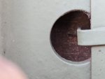
I found the PC mark - it was rusted so a little bit difficult to see - see below.

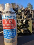
The gear was still turning but with significant resistance and pushing the cap in was very difficult. So I put some Chemtool into the fuel intake hole and gently shoke the whole assembly from side to side. In less than 10 minute the difference was dramatic - the gears spun easily and the cap pushed in and out with little resistance... I hope I did not break it in the process,
PXL_20220218_210719482.jpg

PXL_20220219_222849887.jpg


Keep turning the motor. "B" is for setting the valves. You want "PC" on the flywheel. Get it on the PC mark and then verify the position of the #1 intake cam lobe in the picture I posted.

Most pumps will spin pretty easily with just 2 fingers to turn it. If it requires your whole hand to crank on it then that is abnormal.
does the cap that rides on the cam lobe press in and out ok? That requires some force but should move in and out, activating the plunger.
 

GAPRIME

Member
41
26
18
Location
GA
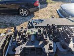
Progress so far with a lot of help from my gurus & friends -
  1. Tank cleaned out, coated with Caswell plating epoxy folllowing Ray's direction and reinstalled.
  2. Cylinders emptied of water, cleaned, engine released
  3. Head cleaned and machined remounted with the rockers
  4. Injector pump degunked and installed
  5. Fuel lines installed back on the IP and injectors
    1. Two lines were so difficult to remove they got twisted - replaced with new fabricated brake lines.
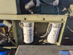
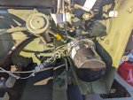
  6. New spin-on fuel filters and oil filter from Ray70 - true drop in replacement with a little bit of elbow grease (y).
  7. New gaskets, o-rings, glow plugs from the kit recommended by Chainbreaker (y)
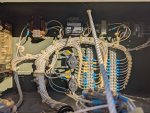
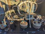
  8. Quick inspection of the electricals - was shocked by how clean those compartments were.
Planning to put the exhaust cover back on, add oil, connect the batteries, connect Baldwin air filter kit, testing the fuel pumps and bleed the fuel system and then the moment of truth...

Thank you all for all the tremendous advice and coaching... Irrespective of the outcome this has been a very rewarding experience.

PXL_20220219_204213880.jpgPXL_20220219_221947424.jpg

PXL_20220219_222019014.jpg

PXL_20220219_204155613~2.jpg

PXL_20220219_221806748.jpg
PXL_20220219_221800459.jpg
 

Chainbreaker

Well-known member
1,802
2,009
113
Location
Oregon
Looks ready for liftoff soon!

I'm sure you know this but... make sure the batteries are fully charged & remember when starting to allow glow plugs & intake heaters a good 45 - 60 seconds preheat & most importantly hold start switch while cranking, and its running, until oil pressure builds and then release. EDIT: It seems contrary to continue to maintain start cranking switch position, however it has a starter lockout by design, so starter is not engaged after a certain RPM is reached. In the Start position the low oil pressure switch is bypassed to allow oil pressure to come up.
 
Last edited:

GAPRIME

Member
41
26
18
Location
GA
You all know your stuff!!

Fuel check
- Tank to pump outlet - CHECK​
- Fuel filters to fuel outlet - CHECK​
- Fuel to injector return lines - CHECK​
Oil Check
- Oil level check​

Electrical
- Batteries connected with correct polarity - CHECK​
- Instrumentation lights - CHECK​
- Prime - Check​
= Start position - FAILED. Maybe weak batteries?​
= Jump starter - engine kicks, turns over no start. Repeat x4​
= Jump starter - sniff gasoline on intake manifold​
- First test - no go​
- Second test - no go​
- Third test - no go - wait a minute was that a cough?​
- Fourth test - come on you can do it...............​
- SUCCESS!!! Machine running, shaking, roaring, belching smoke like tear gas​
- WOW!! I can't believe it!​
- Then the generator had a mistaken identity and thought it was a Chopper started revving really, really high. Chainbreaker you are spot on!​
Panic - Turn switch to off, Press emergency shut off...

Tried to restart again but no go - think it might be weak batteries - what's the recommended size, crank power for these batteries?

Still to do
- Get two recommended batteries.​
- Check switch and wiring to see why it would not start without jumping the starter.​
- Starter solenoid may need to be repaired​
Thank you for all your help so far - please share any additional tips and recommendations


Looks ready for liftoff soon!

I'm sure you know this but... make sure the batteries are fully charged & remember when starting to allow glow plugs & intake heaters a good 45 - 60 seconds preheat & most importantly hold start switch while cranking until oil pressure builds and then release.
 

Chainbreaker

Well-known member
1,802
2,009
113
Location
Oregon
Its alive, its alive!

Could be someone messed with the engine Speed Control knob if it was revving very high or there are linkage issues.

If RPM's are way off you push in or out on the center button on knob to raise or lower RPM, or you can do fine adjustments by twisting the knob to the right or left as needed to get 60 Hz on Panel Meter or Kill-A-Watt plugged into convenience outlet. 60 Hz = 1800 RPM

Also, you should check the linkage arm going to governor located under the "Close To Run" cover. Make sure the spring is about midway on the worm gear and the star nut is a few threads up above it. In the -12 TM there is a picture on PDF Page # 94 that shows the spring & governor linkage and about where it should be set as a rough reference.

Also, visually inspect the ball joint linkage going to stop solenoid. Sometimes those get broken or badly worn.
 

Chainbreaker

Well-known member
1,802
2,009
113
Location
Oregon
Panic - Turn switch to off, Press emergency shut off...
BTW, the S1 "Master Switch" should shut it down when turned to "OFF". If it doesn't, you can pull on the "Emergency Shut Off Switch" to activate it which cuts power to Fuel Solenoid and I think to Fuel Pumps (The DC Control Circuit). Pushing in resets it when it has been used to shut off (tripped).
 

Chainbreaker

Well-known member
1,802
2,009
113
Location
Oregon
Also, on the battery size for your -003a... I'm not 100% sure but for some reason "Group 24" sticks in my mind as an alternative to the Mil Spec batteries that were used.

Also, there are a lot of maintenance items covered in this thread in the -003a section.
 

Ray70

Well-known member
Steel Soldiers Supporter
2,634
6,060
113
Location
West greenwich/RI
Correct, group 24 fits pretty good. The originals were 6TL which were essentially a cube rather than a rectangle.
You can still get them from several places but it will be a special order and they can be pricey.
Although my commercial price at O-Riley's was about $200 last time I checked, so not too bad at some stores.
 
Top
AdBlock Detected

We get it, advertisements are annoying!

Sure, ad-blocking software does a great job at blocking ads, but it also blocks useful features of our website like our supporting vendors. Their ads help keep Steel Soldiers going. Please consider disabling your ad blockers for the site. Thanks!

I've Disabled AdBlock
No Thanks