• Steel Soldiers now has a few new forums, read more about it at: New Munitions Forums!

  • Microsoft MSN, Live, Hotmail, Outlook email users may not be receiving emails. We are working to resolve this issue. Please add support@steelsoldiers.com to your trusted contacts.

MEP-003A hook up question

MidKnightBomber

New member
42
0
0
Location
Salt Lake City, Utah
I understand the purpose of differentiating between a SDS and a non-SDS setup.

Question:

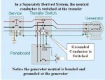
Looking at this picture of an SDS system that has a grounding rod at the generator and the service entrance:

It appears to me that whether the generator is running or not we can trace a continuous electrical path from the generator grounding rod, through the generator neutral buss, through the green line (grounding wire) and subsequently through the service entrance neutral buss and into the grounding rod at the service entrance side.


Doesn't this effectively create a 2 grounding rod setup? I Thought two grounding rods were bad? In this photo the two grounding rods are common at the service entrance. Correct? ImageUploadedByTapatalk1398531923.823249.jpg
 
Last edited:

pclausen

Well-known member
Steel Soldiers Supporter
452
281
63
Location
Afton, VA
Hi guys,

Tomorrow I'm picking up an Asco 300 Series 200A transfer switch. It is unfortunately not Service Entrance rated (doesn't have service disconnect in it). So that's challenge #1. Challenge #2 is that I'm wanting to feed 2 200A panels with it.

I think my meter base is a 320A or 400A unit and it is mounted directly behind the 2 200A panels on the outside.

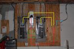
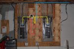
Here are some pics of how I was thinking I could mount the transfer switch:

Scenario 1 - Leave both 200A panels where they are. This would maybe allow me to add a service disconnect in-line between the meter base and transfer switch.

dual200-1.jpg
http://www.cstone.net/~dk/dual200-1.JPG

Scenario 2 - Move the right 200A panel over a little to make room for the Asco to fit in between. This scenario will not allow for a service disconnect, but will make for a much cleaner install.

dual200-2.jpg
http://www.cstone.net/~dk/dual200-2.JPG

In both scenarios, red lines indicate utility power, yellow is load power and blue is generator power.

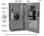
Here's what the Asco switch looks like inside:

asco200a.jpg
http://www.cstone.net/~dk/asco200a.JPG

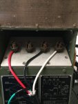
And the meter base with the meter and cover removed:

generac2.jpg
http://www.cstone.net/~dk/generac2.jpg

And here's the not-so-safe way I was connecting my PTO generator to the meter base. No, I'm not doing it like this anymore.

generac1.jpg

As you can probably tell, the power company is pretty lacks about me going into my own meter base. I plan to do the work myself and already have enough 3/0 AWG laying around to wire it either way.

There's no way in a million years I'd every pull even close to 200A from both panels combined. The reason I have 2 panels is just due to the number of circuits in the house. Main level HVAC system was replaced last year with the 20 seer heatpump that sips power compared to the old 4ton 10 seer unit it was replacing. Cooking and water heater are both propane.

My plan is to use a pair of 2 into 1 lugs to feed both panels from the load connectors on the transfer switch.

So how big a deal is it to not have a service disconnect switch? When performing the actual work, I of course plan to pull the meter so that there is no power as I run the 3/0 wires.
 
Last edited:

jimbo913

Active member
281
37
28
Location
Maryland
Confusion on quote

"I did have an electrician come by, his help kept me from miswireing a couple breakers when I moved them for the Interlockkit. (separate circuits w common neutral have to be on alternating breakers in panel) Glad I called him."

I was a bit concerned when I read this post because I too moved some breakers around for my interlock kit. I didn't realize it mattered where breakers ended up in the box. Anyone have examples of items that would have "separate circuits with common neutrals" and what alternating the breakers means? Do the breakers have to be on opposite sides of the panel directly across from one another?

I back feed through a 50A 240V breaker, and it appears to operate my entire panel box, as well as sub panel. Of course I turn off all 50A and 60A breakers when using the generator.
 

lxawolf

Member
44
1
6
Location
Sussex, NJ
I can not think of an example of a load that would use separate breakers but have one common neutral unless going to a sub panel that has a double breaker and a separate unbounded ground and neutral.
There you would have 4 wires 2 hot neutral and ground all going back to your main panel where the neutral ground bond would be. I think what the alternating the breakers. When you look at the bus bar the breakers into each slot hooks onto 1 of them. So by that logic the breakers in 1,3,5 position ect will be on the same line and 2,4,6 ect will be on the other.

This does not matter for your 120v loads. (you do want to at least match somewhat when you install, so your generator is using all windings at around the same level) the only time positioning is important is your 240v load. You would not get 240v if you took 2 seperate breakers and put them in position 1 and 3. But the NEC requires a double or a physical connection to make 2 single act as a double.

Actually the only thing that I can think of if you turned an older 240v outlet for a say a dryer into two regular outlets you could potentially have 2 120v outlets on a former 240v circuit. Assuming you put in all appropriate steps to deregulate the amperage to 15a or 20a. However I am not sure if that is even legal under the NEC.
 

212sparky

Well-known member
1,822
38
48
Location
Monroe/ Ohio
I can not think of an example of a load that would use separate breakers but have one common neutral unless going to a sub panel that has a double breaker and a separate unbounded ground and neutral. There you would have 4 wires 2 hot neutral and ground all going back to your main panel where the neutral ground bond would be. I think what the alternating the breakers. When you look at the bus bar the breakers into each slot hooks onto 1 of them. So by that logic the breakers in 1,3,5 position ect will be on the same line and 2,4,6 ect will be on the other. This does not matter for your 120v loads. (you do want to at least match somewhat when you install, so your generator is using all windings at around the same level) the only time positioning is important is your 240v load. You would not get 240v if you took 2 seperate breakers and put them in position 1 and 3. But the NEC requires a double or a physical connection to make 2 single act as a double. Actually the only thing that I can think of if you turned an older 240v outlet for a say a dryer into two regular outlets you could potentially have 2 120v outlets on a former 240v circuit. Assuming you put in all appropriate steps to deregulate the amperage to 15a or 20a. However I am not sure if that is even legal under the NEC.
Your breaker locations should be 1,2 A phase. 3,4 B phase and so on a single phase system. So when you snap in a 2 pole breaker it hits the 2 different phases. I hope this clarifies that for you, if you have any other questions PM me.
 

Razerface

New member
61
0
0
Location
Urbana, ohio
I have been checking my system with this thread. I am unbonding my mep. I have noticed that every single box in my system has a green bonding screw in it. After the meter there are 3 different breaker/disconnects going to 2 barns and house. All of them have the bonding screw in them. Take them out?
 

lxawolf

Member
44
1
6
Location
Sussex, NJ
With that setup it might be best to consult an electrician.

It's tough to say what to do in your situation with out further information.
Some places allow double lugging, this is basically two sets of wires are coming from your meter base and going to two different load centers or breaker boxes. This is more common in a 400 amp meter base. As 2 200 amp load centers are less expensive.
If this is your setup then they would need to be bonded as each load center is a separate derived system. Unless they are bonded at a disconnect or in the meter base. Once again it all depends on NEC and local codes. They would each require grounding rods, ect.

However if they are connected meter to load center 1, breaker to wire to load center 2 ( sub panel) then they need a 4 wire system and not to be bonded at each load center.

So more info is needed. But I would consult an electrician before you start changing things in your electrical system.
 

Daybreak

2 Star Admiral
Steel Soldiers Supporter
1,522
771
113
Location
Va
I have been checking my system with this thread. I am unbonding my mep. I have noticed that every single box in my system has a green bonding screw in it. After the meter there are 3 different breaker/disconnects going to 2 barns and house. All of them have the bonding screw in them. Take them out?
Howdy,
I would suggest getting a electrician out to your place.
Your configuration sounds like mine, and I do not think you could explain enough here to have anywhere as a complete correct answer (internet answers are iffy) Grounding is important for you and equipment.

note: due to distances from the meter, barns and shops and other buildings can have another ground at that panel. (this is a variable due to local codes)
 

two.fiveM35

Active member
1,234
11
38
Location
Victoria , Texas
After much reading in this forum I finally and carefully hooked up the generator to the house. I started slow, after checking polarity, hz,and voltage, I slowly turned on a frig, freezer, tv and cable box in the garage and all worked fine.

Next switched on the 5 ton a/c and then the 3.5 ton a/c. Still everything was fine and load was only at 60%. This gen is awesome and thank to youguys for all the advise.


image.jpgimage.jpgimage.jpgimage.jpgimage.jpg

Quick note, the black wire connected to the ground lug is actually an extension of the ground wire, black was the only color they had.
 
Last edited:

jamawieb

Well-known member
1,435
557
113
Location
Ripley/TN
May I ask why you unhooked your isolated ground for the generator head? In the picture you took of the ground stud, you have it disconnected and wrapped in electrical tape. I believe that really needs to be connected back to the ground stud, on the frame.
 

two.fiveM35

Active member
1,234
11
38
Location
Victoria , Texas
May I ask why you unhooked your isolated ground for the generator head? In the picture you took of the ground stud, you have it disconnected and wrapped in electrical tape. I believe that really needs to be connected back to the ground stud, on the frame.
Wish I could explain it properly, but it's explained earlier in this thread several times. I have a "non separately dirived system" and it said to unhook the neutral bond at the frame. The frame is still grounded by the wire that runs thru the house ground to the house grounding rod
 
Last edited:

hammick

Member
130
2
18
Location
Missouri
Anyone who is buying and using these generators should get help from real electrician if they are not sure of what they are dealing with when hooking to grid.
Some electricians don't know the ins and outs of grounding. When we finished our basement we had a sub-panel installed next to the main panels. The electrician bonded neutral to ground in the sub-panel and didn't run a ground wire from the main panel. I did a lot of reading on grounding and fixed it myself in about five minutes.

The electrician did know enough not to mix the neutrals and grounds on the bus bars of the sub-panel. Had he mixed them it would have been a nightmare to correct.
 

wsmolloy

New member
5
0
0
Location
West Palm Beach FL
I just picked a MEP-003A, I understand the hook up that Coyotegray posted (great info).

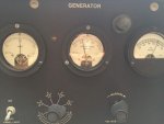
I am getting the correct voltage. I understand you need to increase the throttle to get 60HZ. My gauge stays to the far right 65HZ whether I have it at low idle or high.
Any idea why the HZ will not adjust?
I don't what to over feed my house. Mt throttle will effect the voltage out put but not the HZ. Hoping it is nothing more than a bad gauge.
 

derf

Member
926
13
18
Location
LA
Put a meter that reads frequency on it. You can get cheap volt/frequency meters online that you can use to upgrade from the original.
 

wsmolloy

New member
5
0
0
Location
West Palm Beach FL
Thanks, I will see if my meter reads HZ, Are you saying to read it on the back of the existing gauge? can you suggest a place to get a new gauge online if that is the problem. We might have a storm coming to So. Florida and I want to be prepared.
 

derf

Member
926
13
18
Location
LA
I use something like this:
https://www.amazon.com/KETOTEK-Voltmeter-AC80-300V-Frequency-45-0-65-0/dp/B01D891MHO

You should just read the output to get accurate frequency. Some gens have a sender and a meter that reads the signal sent from the sender so you may not get an accurate reading from the back of the gauge. You can look at the schematic to tell. IIRC, the MEPs have senders but I may not be correct on this.
You may first look to fix the existing frequency meter but you may soon find it more expensive than just adding an easy to read, inexpensive, modern digital volt and frequency meter.

In general:
Engine RPM determines frequency.
Voltage can be adjusted with a knob.

Some of this stuff is 50s-60s technology. Adding a modern gauge can be a good thing.
 
Last edited:

wsmolloy

New member
5
0
0
Location
West Palm Beach FL
I am going to see if I can find something like this locally any ideas what type of store would have this? With the possibility of a Storm coming to Florida I want to run my house without damaging anything. What am I looking for on the schematic, IIRCV could you explain.
 
Top
AdBlock Detected

We get it, advertisements are annoying!

Sure, ad-blocking software does a great job at blocking ads, but it also blocks useful features of our website like our supporting vendors. Their ads help keep Steel Soldiers going. Please consider disabling your ad blockers for the site. Thanks!

I've Disabled AdBlock
No Thanks