• Steel Soldiers now has a few new forums, read more about it at: New Munitions Forums!

  • Microsoft MSN, Live, Hotmail, Outlook email users may not be receiving emails. We are working to resolve this issue. Please add support@steelsoldiers.com to your trusted contacts.

MEP-004a 005a over voltage after single phase conversion

jskiff1

New member
10
2
0
Location
Mpls. MN
Hello. I'm a new poster so please be gentle.
I will start with a brief history:
I was able to get a nice deal on a MEP-005a and trailer that was missing the voltage regulator. I installed a MTS ADVR-054 voltage regulator and a SS500 static exciter. It worked great on three phase 208/120.
I then went for the single phase conversion described in great detail by Sewerzuk and a few other members. Thank you all for your contributions, this was a great piece of work. Anyway, the unit starts and flashes but the unit goes into an over voltage shut down a few seconds after starting. It will recover after the shutdown drops the RPMs and voltages only to shut down again. I suspect this is hard on things and I don't want to make changes until I have a firm handle on the problem.

So, to my way of thinking the changes on the reconnect board are no longer giving my voltage regulator the 208-240 volts it needs. I expect the pin M (X8HH16B) and the pin L (X3J16C) connections I am using are not connected to T1 and T3 as would be needed in the new configuration. This is where I am getting into trouble. The wiring diagrams in the TMs suck. There is no page that I can find that shows the J13 plug (VR Cannon plug) wiring going into the reconnection board. Are these two wires really T1 and T3 or do I have something mixed up? I strongly suspect I am connected to T2 with 1 lead, which of course is not being used in the new configuration.
Both of VR-static exciter and the zigzag mods are quite common and I wonder if anyone else has already figured out what is wrong. Can anybody out there help?
:-(
 
Last edited:

jskiff1

New member
10
2
0
Location
Mpls. MN
I had not but I just did. From what I see I cannot determine the circuit that is feeding pins M and L on j13. I was hoping for a visual wiring diagram. Where do they originate? Are there other pins that are connected to T1 and T3?
 

Guyfang

Moderator
Staff member
Moderator
16,697
23,916
113
Location
Burgkunstadt, Germany
On page 5-53, there is a picture of J-16, with wire numbers and end terminus. There is also a picture of T-1 and T-3. Also, if the pictures and printing is hard to read, due to being copied 10 million times, go to the 15 KW manual, its lots cleaner to read, and there is no difference between the sets.
 
Last edited:

jskiff1

New member
10
2
0
Location
Mpls. MN
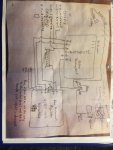
IMG_0534.jpgThis is better but I believe it shows the wiring that was once inside the VR cabinet. T-1 is the 8 segment connecter that was wired to all the components that I have removed when I put in the new VR. My new VR got rid of most of the things shown
 

Guyfang

Moderator
Staff member
Moderator
16,697
23,916
113
Location
Burgkunstadt, Germany
FO1, Page FP-7, Shows me that J-13, pin M, goes to TB6-8 and J-13, pin L, goes to TB6-9. I assume you used the original wire harness, and did not supplement it?
 

jskiff1

New member
10
2
0
Location
Mpls. MN
I am using the unmodified harness, of course with the single phase reconnects. I am assuming that TB6 is the reconnection board. I might go about this in a backwards manner. I can use my meter to ring out T1 and T3 and see if i have connections to J13. I will also look at T2 and see if it shows any continuity to my wiring. This will need to wait until tomorrow. I will post my findings. Thank you, You know your way around the TMs a lot better than I ever will.
 

Guyfang

Moderator
Staff member
Moderator
16,697
23,916
113
Location
Burgkunstadt, Germany
Correct. TB-6 is the reconnection board. That's what I thought you were going to do, ring it out. I guess you could say I worked on this set a while. I still bang my head with schematics, I am dyslexic. Like I said, the 15 KW books are of a better quality. Keep us informed. I just love these gen sets!
 

jskiff1

New member
10
2
0
Location
Mpls. MN
OK, I got busy this morning and tried to find which terminals my VR was actually connected to. To do that I just connected to the tb6 side of the main contactor and went right to the VR connections. after disconnecting the VR, I found my AC inputs with continuity to all 3 legs. ???? OK maybe I am seeing continuity through the generator windings. Not easy to isolate. So, plan B.... I removed my single phase modifications and tried the genset as it was when it was working. Same problem, over volt fault and the under frequency led on the VR was flashing. Thinking that I had smoked my new VR I removed it and tried it on another generator, lucky I have two. The VR worked on the 2nd. unit. Rule out bad VR. Now I am going to back off and let things settle in my brain for a day, sometimes that helps. I will probably have a look at my original mods for single phase and make absolutely certain I didn't boot something. If anyone has any ideas what I should look for please let me know your thoughts. Thanks
 

Guyfang

Moderator
Staff member
Moderator
16,697
23,916
113
Location
Burgkunstadt, Germany
Never hurts to take a breather and think on it.

It sounds to me like you have a wire, someplace, hooked up wrong. And yes, I think you are getting continuity by reading back through the windings. I always disconnect both ends of a wire to ohm it out. Continuity can be a liar, sometimes, when you don't.

When you did the mod to make it single phase, you take the TB-6 apart? Its easy to get a wire wrong on the TB-6, because there are more than several there. Do you still have all the original parts? Can you put it all back together, like it came from the factory? When ever I had to go fix something that someone else had worked on, when I had a problem like yours, I put it all back together just like it was to start with. Then started from scratch. Any wire you moved, removed, added, and so on, is suspect. I had a problem, (self inflicted) once, and it was a voltage problem, and the only thing it was, was a wire connection on the TB-6, had shifted, when I tightened it. It then made a tiny bit contact with the next terminal. You could hardly see it was there, but it sure didnt work! If this thing worked at the beginning, then it probably is just a small mistake, brought on by the mod. In the original setup, over volt, under freq, was a static exciter problem. All you did was upgrade the static exciter, so I think its got to be in there, the upgrade. You have proved the volt reg, so it take a large part out of the equation.
 

jskiff1

New member
10
2
0
Location
Mpls. MN
OK, I have partial success. I booted the conversion back to 3 phase. A guy need to clean up the reconnection board. The terminal numbers are progressive on every other row. I had some stuff hooked up to #5. I corrected it and it ran in 3 phase beautifully. Nothing was blown up.
Now onto the single phase conversion. Same problem as before, over voltage trip after a couple seconds. I backed off the voltage regulator to its low limit on the trimmer pot and was able to get it to not trip but I measured 370 volts from L1 to L3 on my meter. I triple checked the wiring and found it to be perfect.

I think I am back to finding the L1 and L3 connections going into my VR cannon plug. If I can identify the circuit on the reconnect board I can run a test jumper and not go through the harness. It went better after sleeping on it last night and it runs just fine the way I have it now in 3 phase. I will sleep on it again and try another stab at it later. I still think the conversion switched the voltage from 208 to 120 or none on my VR AC input. If I reconfigure to single phase again I might be able to verify low volts on my VR input and maybe even find 240 volts in the plug but I really hate to stress the set at 370 volts while I work on it. Any ideas?
 

Guyfang

Moderator
Staff member
Moderator
16,697
23,916
113
Location
Burgkunstadt, Germany
Take a picture of TB-6. Or just look and see what position is it in? 120/208 or 240/416?

I looked at FO-1, sheet 4 of 4, page FP-7. It shows on the far right side, top of sheet, J-13, and where all 11 wires get hooked up. It shows TB-6, and where all its wires come from, and go to. This is naturally three phase. Only four, (4) wires from J-13 go to anything but the CT's. The CT's are for measuring purposes only, for the VR. Wires S&R are for to the F-1-16, and F-2-16, on TB-16(exciter field). So this only leaves Pins L&M. They go to TB-6, pins 8&9. Rather than running wires extra, take the wires off the TB-6, and ring them, point to point. Also read note #4 of the schematics, up top by the legend.
 

jskiff1

New member
10
2
0
Location
Mpls. MN
Wow, that sounds like the exact info that I needed. TB6 8 and 9. The info you just gave me fits perfectly with my wiring diagram for the AVR/SE.
I can find the leads from the VR quite easily now. Once I have them Identified I should just need to bring them to terminals 1 and 3 on the TB6.

I don't know how you found that page. I never got close. I need to print them out. Which manual is this from? I don't know what FO-1 and FP7 are.

Your the Man!
 

Guyfang

Moderator
Staff member
Moderator
16,697
23,916
113
Location
Burgkunstadt, Germany
This stuff is easy, when you take your time. If this dyslexic old soldier can find it, so can you. You just need to download all the TM's from the SS TM section, and look through them. It's all a matter of having the latest books, with the latest change to them, and half the battle is won. Whenever I work on a MEP-004A or a MEP-005A, I use the -004A TM-5-6115-464-12, dated 30 july 1993, with change 2, for troubleshooting. The schematics are in the back. If you are going to do a LOT of work with the gen set, spend the money to get the -12 manual printed out. And the schematics enlarged. They are very much easier to read that way. We always got them covered in acetate, so they were water and dirt protected. FO-1 and FP-7 are page numbers.

Use the right parts TM, -24P for whatever set you have. 95% of the parts are interchangeable between the 004 and 005 gen sets, but still, get the right -24P for your set. The -34 manual is the same for both 004 and 0045. Interchangeable. Once you spend some time looking through the books, you too will be able to find what you want.

Keep us informed. If you have any other problems, shoot us a line. The only dumb question, is the question not asked.

Take care partner, and hope you have a nice day!!

Guy Wiltfang
 
Last edited:

jskiff1

New member
10
2
0
Location
Mpls. MN
Sweet victory at last....
Your info was spot on. One lead from the J13 plug rang out to XA16B which Sewerzuk had instructed to move to T3 on the reconnect block. This works.
The other lead rang out to X8HH16B which the instructions said to move to T11. This is incorrect for my configuration. I moved the lead instead to T7 (T1 is in parallel so it would be correct too). I don't see why moving it to T1/T7 would not work in three phase as well, but I'm not going to mess with it now that it is working. I'm still afraid of smoking something if I goof up again.
Thank you for all your hard work effort and learned skills that made this possible. Maybe we should invite Sewerzuk into the conversation for comments. I might not be the only one out here that is using a non OEM VR/SE that would like to make the single phase conversion.
 
Last edited:

rickf

Well-known member
Steel Soldiers Supporter
3,132
1,634
113
Location
Pemberton, N.J.
I want to say I really enjoyed this and will bookmark it since I have plans on picking up an 04 or 05 in the near future. Can never have enough information.
 

Guyfang

Moderator
Staff member
Moderator
16,697
23,916
113
Location
Burgkunstadt, Germany
Good to hear!

You know, you would have figured this out with a little more time. If you can read, you can fix a gen set.

So what all are you going to do with your gen sets. If you ever get a chance to scrounge up a extra Special Relay Box or a S-9 Speed Switch do it. The same with other components. Its way easier to change a relay box, then to troubleshoot at 03:35 in the morning. And when its a civilised hour, you can then figure out what's wrong, fix it, and have a running spare again. One of the real nice things about this gen set is that the electrics are broken down in the parts TM, and you can actually fix things. The -34 explains how to test everything. Good luck partner, and take good care of the old girl, and she will be nice to you!

guy
 

jskiff1

New member
10
2
0
Location
Mpls. MN
I am trying to make some retirement income using learned skills. I have 2 units, both on trailers. Up here in northern Minnesota the power lines are long and are overhead. Lots of power outages. Resorts up here may have bookings a year ahead of time. So - Jim to the rescue. If a storm shuts off power to the resort I can pull a unit to the site, Business as usual. Resort has income, I get some of it they would otherwise not get. I would charge plenty. The resorts are typically at the end of lines and are single phase so the single phase part is quite important. I gave up too much already. I am just really happy to have you folks providing the knowledge of your years of experience.
 

rickf

Well-known member
Steel Soldiers Supporter
3,132
1,634
113
Location
Pemberton, N.J.
I like old military stuff but for what you are proposing I would think a commercial unit would be more in line. Liabilities are the first thing to come to mind using a modified generator in a commercial setting. BIG time liabilities!
Not to mention you are going to need a lot more than 15 KW in a commercial setting plus a license to tie it in.
 
Last edited:
Top
AdBlock Detected

We get it, advertisements are annoying!

Sure, ad-blocking software does a great job at blocking ads, but it also blocks useful features of our website like our supporting vendors. Their ads help keep Steel Soldiers going. Please consider disabling your ad blockers for the site. Thanks!

I've Disabled AdBlock
No Thanks