• Steel Soldiers now has a few new forums, read more about it at: New Munitions Forums!

  • Microsoft MSN, Live, Hotmail, Outlook email users may not be receiving emails. We are working to resolve this issue. Please add support@steelsoldiers.com to your trusted contacts.

MEP-004A, No output

Guyfang

Moderator
Staff member
Moderator
16,765
24,069
113
Location
Burgkunstadt, Germany
Yes, then you don't need to buy the transformer as he is part of A11- but I would add the 3AG Fuse to the new A11....
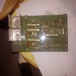
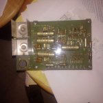
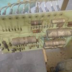
Ok, I am confused. Kris, what does A11 mean to you? Are you talking about the circuit card, (voltage regulator card) you bought? Or the whole box, that was bolted to the relay table, that has the card in it? Because to me, and the parts manual, A11 is the whole box. Maybe I missed a post, but the only thing I remember you buying was the volt regulator card. Unless you have a whole A11, you still need a transformer. Or have I missed something?
 

KLChurch

New member
475
2
0
Location
Montgomery/TX
new trans1.jpgnew trans2.jpg

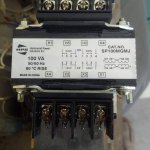
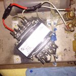
Just got the new transformer in and it got a lot smaller foot print.
No big deal for me because of only drilling new holes.
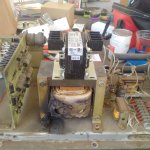
The one atop the toasted will be the replacement
Kris
 

KLChurch

New member
475
2
0
Location
Montgomery/TX
new trans wired.jpg
new trans wired.jpgnew trans wired.jpg
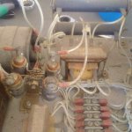
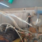
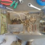
This is the new transformer connected to A11.
Below is the wiring up directions.

1. make a jumper wire
16ga from H2 to H3


2. make a Jumper wire
16ga from X2 to X3


3. connect X12KK
and X12JJ to H4


4.
connect X9Z and X9W to H1


5. connect D12E and
D12D to X2/X3


6. connect P4A to
X1


7. connect P5A to X4

the single wire with no
number was connected to the shield - this wire no longer needed
Put 1 amp fuse between H1 and wires X9Z and X9W
 
Last edited:

KLChurch

New member
475
2
0
Location
Montgomery/TX
With peters help I will be testing the startup.
It maybe best for me to test A5 R3 first. From what I understand it overheated because of the transformer.
I have reinstalled A11 without the cover for visual checking.
The reconnection board is verified to be wired correctly.
The startup sequence is touchy because I don't have the equipment to check it per the manual.
If A11 is still bad I may have to send it to Peter so he can fix it.
I'm going to try to fire up the Gen either Monday or Tuesday.
If A5 R3 is bad maybe longer.
Kris
 

peapvp

Well-known member
Steel Soldiers Supporter
1,113
1,229
113
Location
Basehor, KS
Kris, the entire test procedure is from the -34 Manual you got. All you need to do is to read it and follow it:

b. Equipment Test of Field Flash Circuit Assuming the exciter stator winding resistance is correct (within 1 to 4 ohms)Connect a DC voltmeter (0 to 30 volts) to the two wires that are disconnected from the exciter stator windings. NOTE DO NOT reconnect the wires to leads F1 and F2 at this time.

c. Remove Connector P37 from speed switch. Place a jumper between pins A and C on P37. Momentarily,approximately 10 to 15 seconds, place the START-STOP-RUN switch in the START position and observe the DCvoltmeter. If the voltmeter indicates approximately 24 volts, the probable cause of the field flash is the speed switch. If aDC voltmeter is not available, proceed to step d.

d. Remove Connector P3 from the speed switch. Place a jumper between pins A and C of socket J3 on the specialrelay box for approximately 24 volts DC. If a DC voltage is not present, the problem may be the wiring between the speedswitch and the special relay box, the K5 relay, or current limiting resistor (R35) inside the special relay box (15kW and 30kW generator sets only). If a DC voltage is present, replace Connector P3 on socket J3 and proceed to the next step.

e. Remove Connector P9 from the static exciter/voltage regulator control box. Momentarily, hold the START-STOPRUNswitch in the START position and check between pins C and D of P9 for approximately 24 volts DC. If a DC voltageis not present, the problem may be the wiring between the special relay box and the static exciter/voltage regulator controlbox. If a DC voltage is present, replace Connector P9 on-socket J9 and’ proceed to the next step.

f. Remove Connector P13 from the static exciter/voltage regulator control box. Momentarily, hold the STARTSTOP-RUN switch in the START position and check between pins S and R of J13 on the control box for approximately 24volts DC. If a DC voltage is not present, the problem may be any one of the following items within the control box:

(1) Broken wire within the control box.
(2) Current limiting resistor R219 sets.
(3) Current limiting resistor R17 sets.

g. Reconnect the wires previously removed from the exciter field winding, F1 and F2.
 
Last edited:

KLChurch

New member
475
2
0
Location
Montgomery/TX
F1 and F2 were disconnected The other adjacent wires were not. used a analogue mm connected to F1 and F2 to the wires not the terminal. Start position and the engine started. Left the engine running for 4 secs with the start still on.
No volts between F1 and F2.
 
Top
AdBlock Detected

We get it, advertisements are annoying!

Sure, ad-blocking software does a great job at blocking ads, but it also blocks useful features of our website like our supporting vendors. Their ads help keep Steel Soldiers going. Please consider disabling your ad blockers for the site. Thanks!

I've Disabled AdBlock
No Thanks