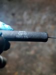
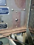
So I have a 005a that roasted the T2 transformer in the Static Exciter / Voltage regulator assembly. T2 is the large transformer inside the exciter/regulator assembly. I'm converting the entire VR system to a new self exciting automatic Voltage regulator. The regulator is a ADVR-054 and its a simple install with a 4 wire hook up, I need 2 for sensing (voltage) and 2 for the exciter. But the schematics on the 004a and 005a are junk. I need some help identifying the wires I need, I'm looking for the 2 wire hook up for the exciter. I believe I can use A and B in J9 connector for the connection to the exciter. The confusion is coming from the Bench testing diagram in TM -34 (3-page 284) for the 004a. From the diagram, it looks the voltage comes from the VR to T3 (X1 and X2) then flows out of T3 at H1 and H2 going to the exciter.
Then I need to find 2 sensing wires that actually read the voltage. I believe I can use L and M from J13 for those.
I just wanted validation before proceeding further.
The 004a manual is cleaner to read than the 005a.
Then I need to find 2 sensing wires that actually read the voltage. I believe I can use L and M from J13 for those.
I just wanted validation before proceeding further.
The 004a manual is cleaner to read than the 005a.


