This is going to be a picture tutorial on the speed switch. There are two different kinds some units have an electronic version which has a more square enclosure and the mechanical version which is a round casing. This is going to be covering the round mechanical version I used to have a unit with the electronic one but sold it years ago it had its own issues got it wet once and had to replace a couple components on it to get it to work. Any way
So I ran into a problem the other day where my 005a would not crank over. I first had assumed it was starter solenoid however that turned out to be just fine and then I dug into the TM and it wont lie it leaves a lot to be desired in the troubleshooting section. It literally said probable causes was the K3 relay, or the CR3 diode then the starter and if none of those were it you are pretty much SOL. Well I tore all those parts out and verified they were good all working just fine still no go from the start switch. Well after searching for hours and trying to trace out the wiring diagrams on the panels turns out it was the speed switch. I happened to have a completely corroded speed switch from another unit I sold years ago but I knew it was good except for the broken shaft because it was seized up. So I swapped it out and what do you know the generator cranked right over. So problem isolated to the speed switch. Well I found one but the guy wants 400 bucks and I decided I did not really want to pay that unless I actually have to.
Well I could not find any info on this switch let alone anybody that has opened it up to fix it.
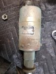
Here is the switch and what the mechanical one looks like this one is is really bad shape so decided id crack it open first before I opened up the unit on the actual genset so I could see how it was put together.
So First step is cracking this thing open. You will notice three recessed screws on the top of the unit. One was phillips the other was flat head but both are the recessed style screws unscrew them and then slit the tape that holds the upper housing to the lower housing and you will then pull and the top part of the housing will separate from the lower part of the housing and a wiring harness will still hold the two together. You will then notice there are three nuts around the edge do not touch these. They are pre set with springs and plungers that go down through the switch body to give different resistance to the microswitches in the other half of the unit. You will see 3 small hex screws in a triangle shape more toward the middle you will want to remove all three of these to release the switch plate in the part of the housing.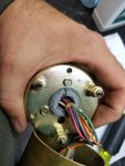
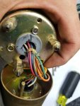
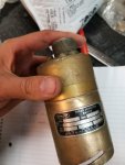
Now you need to move to the lower part of the housing you will notice there are three screws with hex heads holding the housing together and there are slanted slots. These screws have a safety wire running through them you will need to cut the safety wire and pull it out of all three of them. Before you loosen the screws make a witness mark on the housing and the lower portion that it slides over like this.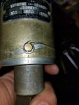
Now loosen these three screws and take them out and simply pull the two pieces apart the lower part is held in with a large oring that keeps dust and dirt out. The lower half contains the weights that spin and push up on the switch plate when the motor is up to speed just put it aside you do not need to do anything with this part. You will now notice on the inside of the housing you separated there are three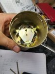
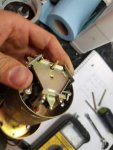 microswitches arranged in a triangle with a triangular plate that the weighed shaft pushes on. You should be able to pull this cluster of switches out since you took out the three screws that hold them in place.
Okay now this is where the problem was with my switch there is a small switch with a lever actuator with white, red, and blue wire running to it. The microswitch has a NC position that was failed and thus not allowing the start switch on the panel to engage the K3 relay and thus turn the engine over. Basically, the unit thinks the motor is running because the NC contact is open since it has failed. Here is a picture of the switch I am talking about.
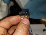
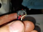
So the microswitch is made by Burgess I contacted them turns out the V4T7 is obsolete no longer made. I did however find a couple of them on the great big auction site. However shipping was outrageous so I just used the one out of the highly corroded speed switch I already had since it still worked. Basically just unsolder the wires and solder in the new switch and bolt the whole cluster back together. When putting the cluster of three switches back in positoin make sure the overspeed switch lines up with the reset hole. The overspeed switch is the one with the yellow and green wire running to it. You will notice when you push it up it stays and you have to push it from the other side to reset it. This is what the reset button does on the top of the housing. Any way put it back in and line up the three screws tighten it down then put the top back on its a really tight fit over the three hex nuts aorund the edge that are numbered. Make sure the wires in the wiring harness do not impinge on free movement of the rod for the reset button or the overspeed switch may not activate if the motor overspeeds due to the weights might not be able to over come the static coefficient of friction on the rest rod caused by the wires pushing against it. So make sure its free to move up and down easily. Put the three recessed screws back in to hold the top part of the housing back on.
Then slide the lower part back into the lower part of the housing now this is where that witness mark is super important. Line them up exactly because it changes how high or low the housing is on the lower part which changes how much throw the weights have to activate the various switchs. Tighten down the three screws and safety wire them back in place. Then put some tape around the upper part of the housing seem to keep dust out and your switch should be repaired.
Hope this helps somebody in the same boat I was in.
Good luck
Lee
So I ran into a problem the other day where my 005a would not crank over. I first had assumed it was starter solenoid however that turned out to be just fine and then I dug into the TM and it wont lie it leaves a lot to be desired in the troubleshooting section. It literally said probable causes was the K3 relay, or the CR3 diode then the starter and if none of those were it you are pretty much SOL. Well I tore all those parts out and verified they were good all working just fine still no go from the start switch. Well after searching for hours and trying to trace out the wiring diagrams on the panels turns out it was the speed switch. I happened to have a completely corroded speed switch from another unit I sold years ago but I knew it was good except for the broken shaft because it was seized up. So I swapped it out and what do you know the generator cranked right over. So problem isolated to the speed switch. Well I found one but the guy wants 400 bucks and I decided I did not really want to pay that unless I actually have to.
Well I could not find any info on this switch let alone anybody that has opened it up to fix it.

Here is the switch and what the mechanical one looks like this one is is really bad shape so decided id crack it open first before I opened up the unit on the actual genset so I could see how it was put together.
So First step is cracking this thing open. You will notice three recessed screws on the top of the unit. One was phillips the other was flat head but both are the recessed style screws unscrew them and then slit the tape that holds the upper housing to the lower housing and you will then pull and the top part of the housing will separate from the lower part of the housing and a wiring harness will still hold the two together. You will then notice there are three nuts around the edge do not touch these. They are pre set with springs and plungers that go down through the switch body to give different resistance to the microswitches in the other half of the unit. You will see 3 small hex screws in a triangle shape more toward the middle you will want to remove all three of these to release the switch plate in the part of the housing.


Now you need to move to the lower part of the housing you will notice there are three screws with hex heads holding the housing together and there are slanted slots. These screws have a safety wire running through them you will need to cut the safety wire and pull it out of all three of them. Before you loosen the screws make a witness mark on the housing and the lower portion that it slides over like this.

Now loosen these three screws and take them out and simply pull the two pieces apart the lower part is held in with a large oring that keeps dust and dirt out. The lower half contains the weights that spin and push up on the switch plate when the motor is up to speed just put it aside you do not need to do anything with this part. You will now notice on the inside of the housing you separated there are three

 microswitches arranged in a triangle with a triangular plate that the weighed shaft pushes on. You should be able to pull this cluster of switches out since you took out the three screws that hold them in place.
 Okay now this is where the problem was with my switch there is a small switch with a lever actuator with white, red, and blue wire running to it. The microswitch has a NC position that was failed and thus not allowing the start switch on the panel to engage the K3 relay and thus turn the engine over. Basically, the unit thinks the motor is running because the NC contact is open since it has failed. Here is a picture of the switch I am talking about.


So the microswitch is made by Burgess I contacted them turns out the V4T7 is obsolete no longer made. I did however find a couple of them on the great big auction site. However shipping was outrageous so I just used the one out of the highly corroded speed switch I already had since it still worked. Basically just unsolder the wires and solder in the new switch and bolt the whole cluster back together. When putting the cluster of three switches back in positoin make sure the overspeed switch lines up with the reset hole. The overspeed switch is the one with the yellow and green wire running to it. You will notice when you push it up it stays and you have to push it from the other side to reset it. This is what the reset button does on the top of the housing. Any way put it back in and line up the three screws tighten it down then put the top back on its a really tight fit over the three hex nuts aorund the edge that are numbered. Make sure the wires in the wiring harness do not impinge on free movement of the rod for the reset button or the overspeed switch may not activate if the motor overspeeds due to the weights might not be able to over come the static coefficient of friction on the rest rod caused by the wires pushing against it. So make sure its free to move up and down easily. Put the three recessed screws back in to hold the top part of the housing back on.
Then slide the lower part back into the lower part of the housing now this is where that witness mark is super important. Line them up exactly because it changes how high or low the housing is on the lower part which changes how much throw the weights have to activate the various switchs. Tighten down the three screws and safety wire them back in place. Then put some tape around the upper part of the housing seem to keep dust out and your switch should be repaired.
Hope this helps somebody in the same boat I was in.
Good luck
Lee
Last edited:


