Scoobyshep
Well-known member
- 925
- 1,011
- 93
- Location
- Florida
Thanks! I plan on doing the single phase conversion after I get it up and running. Will this still work in single phase or will anything need to be changed?
Steel Soldiers now has a few new forums, read more about it at: New Munitions Forums!


Thanks! I plan on doing the single phase conversion after I get it up and running. Will this still work in single phase or will anything need to be changed?

Thanks so much for all the great input!The connection for the 4 power terminals C B B A would be as follows for single phase 240 VAC
View attachment 924815
Follow the Manual for further setup of Dip Switches and adjustments
contact the manufacturer or seller of the ADVR 054 if you have further questions
as to @Scoobyshep ’s comment, he is correct and this is the reason for all the additional parts needed in the above wiring diagram in Post #19.

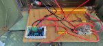
The black fixture is the panel mountable relay socket for the KUP RelayThanks so much for all the great input!
I have already ordered the ADVR 054 and have these items in my Amazon cart.
1- 50 ohm 100 watt resistor
2- KUP-11A55-24 relay
3- 12 ohm 500 watt resistor
4- 1N5408 Rectifier Diode 3A 1000V
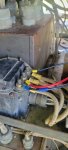
I see the relay is sitting on top of a black fixture. Can someone please tell me what that is and a possible source?
Also, there is a push button in the pictures, can someone please help me with that also?
I have spoken with my electrical engineer buddy and he was really excited to have something to tinker with.
Sorry for all the questions guys, as a farmer I am pretty mechanical, electrical not so much.
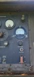
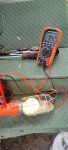
 it has passed that test, but thought maybe hertz would register.
Press button until you see voltage - do not press for more then 2 or 3 secondsI tested as far as according to the regulator manual turn both pots counterclockwise as far as they would go and briefly started the unit just to make sure nothing sparked, smoked or started fire!
I will tape those ends up, thanks.
So, how will I know much how to turn the voltage pot up before I press the button or do I just keep going a little at a time and press the button until I get some voltage?

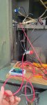
The other one should be terminal number 4 on relay socket to groundI cranked the unit and had only like .6 volts show up on my multimeter. I then pressed the button, saw the relay close, for around 3 seconds and nothing. I then checked the wiring diagram again and seems we have everything correct except looking at the pictures in previous posts there are 2 wires going to ground. We only have 1, I believe we are missing a ground. We have a wire from B on the relay going to a ground and that's it. Can someone tell me about the other one please?

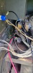
 from the picture it looks rough.
when you do it be sure to wire the AVR sense leads to the single phase configurationThat was it! I just need to adjust voltage tomorrow. I will then do the single phase conversion.
Thanks to everyone so much!
We get it, advertisements are annoying!
Sure, ad-blocking software does a great job at blocking ads, but it also blocks useful features of our website like our supporting vendors. Their ads help keep Steel Soldiers going. Please consider disabling your ad blockers for the site. Thanks!