• Steel Soldiers now has a few new forums, read more about it at: New Munitions Forums!

  • Microsoft MSN, Live, Hotmail, Outlook email users may not be receiving emails. We are working to resolve this issue. Please add support@steelsoldiers.com to your trusted contacts.

Mep 006A won't turn over

Powermaker16

New member
18
4
3
Location
Charleston, SC
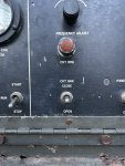
Good Morning Guyfang, Still having issues. I had to take a break on it due to work load. Just started messing with it again yesterday ironically. Fuel being dumped into Oil still and no power lug side of Output contactor. Mentioned above, the leather seals on the injection pump could be installed wrong allowing fuel into the engine. It cranks and runs, blows white smoke. It takes time for the little tank over the injection pump to fill back up each time as it drains down after sitting. I asked in a new thread I had started yesterday ( as I didn't think this was still active) if someone has a diagram or picture how they are supposed to be for when I take it apart. As for the power issue, I figured I would start with the cheapest thing first and replace the "Open Close" switch first as nothing happens when pressed with way.
 

Guyfang

Moderator
Staff member
Moderator
17,490
25,872
113
Location
Burgkunstadt, Germany
I would suggest that you stay with one thread. First off that's the rules, but more importantly, its harder for you to get help. And its important for you to close the loop. If you don't tell us what you have done, then its impossible for us to help you. You need to start on one problem, and fix it. Often that fixes several other problems.

Changing parts is not the answer. It helps the economy, but that's about it. So pick one or the other thread and lets stick with just that thread.
 

Powermaker16

New member
18
4
3
Location
Charleston, SC
The lack of electricity was a new problem which prompted new thread since it was different than my original fuel issue. I want to make sure I can get power, that the electric generator part of this unit is still working before dumping another $1,600 into a new injection pump only to find out I’m not going to get power.
 

FarmingSmallKubota

Well-known member
Steel Soldiers Supporter
544
1,272
93
Location
Wapakoneta, Ohio
The lack of electricity was a new problem which prompted new thread since it was different than my original fuel issue. I want to make sure I can get power, that the electric generator part of this unit is still working before dumping another $1,600 into a new injection pump only to find out I’m not going to get power.
If You want the injection pump rebuilt i would look into Area Diesel before spending that much money on a new one.
 

Ray70

Well-known member
Steel Soldiers Supporter
2,789
6,666
113
Location
West greenwich/RI
The kit to rebuild the IP is like $30 for the basic kit, or a little over $100 if you go with the upgraded metal governor weight basket.
If you only need to replace the umbrella seals that are leaking fuel into the crankcase, those are "external" to the pump and don't require any disassembly of the pump itself, just removing the pump from the engine and replacing the seals on the pump's input shaft.
 

Ray70

Well-known member
Steel Soldiers Supporter
2,789
6,666
113
Location
West greenwich/RI
I am beginning to think the electrical part of this unit is going bad. I feel my rpm’s are high enough to get the 60 hertz I need, but the gauge isn’t moving at all, so I’m thinking it’s a power issue.

Nothing of the kind. It is not an electrical problem. Your throttle cable is hooked up wrong, or its hanging up on something. Do you have a multimeter that reads hertz? How do you feel that the RPM's are high enough? The gage, as mentioned before are not real reliable. But if you have AC voltage, you have hertz.
If you have a Home Depot nearby, for $28 you can get a Kill-A-Watt meter that will plug into the 120V courtesy outlet, it will accurately read volts and Hertz.
Most likely your gage or the frequency transducer that drives the gage is dead.
 

Guyfang

Moderator
Staff member
Moderator
17,490
25,872
113
Location
Burgkunstadt, Germany
You also need to read the -34 TM about how you pull the IP. Its not hard, but read the TM at least twice. Get it wrong, and you will regret it for ever. Say something here before you even get started. We can give you a few tips that will help.
 

Powermaker16

New member
18
4
3
Location
Charleston, SC
So today my gauges read and it said I had 60 hrz. I put a meter on the left side of the breaker and got 470-471 in voltage. Still nothing right side/lug. Tested switch on panel. Seemed to work as it should as it was closed until pressed down and then open. Anything else to check? Ordering injection seals now. IMG_8954.jpegIMG_8951.jpeg
 

Guyfang

Moderator
Staff member
Moderator
17,490
25,872
113
Location
Burgkunstadt, Germany
OK. The AC output Contactor is CB2. The Switch to turn on and off, the CB2 is S3. The light that is suposed to come on, when the CB2 is closed is DS6. The Battle short switch is S7 and the light that is supposed to come on when the S7 is pushed up to turn on the Battle short function is DS7. The DC power cuircuit breaker is CB1.

Now, push in the the CB1.
Turn the S2 to the run position.
Press the DS6 & DS7 in, one at a time. Do they light up, and when you release them, go back out? If so good.
Place the S7 in the up position.
The DS7 should light up.
Then push the S3 up.
You should hear a thunk, when the CB2 closes, and the DS6 should light up.

Do this and tell me what happens.
 

Powermaker16

New member
18
4
3
Location
Charleston, SC
I am a little confused with all the ds6, ds7 etc… so I took a picture of my panel. The circuit breaker switch is always closed and according to the instructions you press it down to open when shutting the unit down. It does move up, but looking at the back of it, there are no wires attached to top leads. Light works, but never seen it lit while operating.
 

Attachments

cbrTodd

Well-known member
Steel Soldiers Supporter
273
494
63
Location
Indianapolis, Indiana
You also need to read the -34 TM about how you pull the IP. Its not hard, but read the TM at least twice. Get it wrong, and you will regret it for ever. Say something here before you even get started. We can give you a few tips that will help.
It may not be 'hard', but I got real tempted to use colorful language trying to get the injector lines on the back side of the pump to break free. I know I bought a special short 9/16" socket and a 3/8 breaker bar for it as well as a 'torque adapter' and a set of curved wrenches. I know the curved wrench didn't help but I can't remember about the others. I know one of them required me using one open end wrench to extend another one and I still ended up having to take the charge pump portion off to be able to get to everything. It *can* be done, and the TM did help, but be prepared for a series of fights getting the injection pump on and off.
 

Ray70

Well-known member
Steel Soldiers Supporter
2,789
6,666
113
Location
West greenwich/RI
I am a little confused with all the ds6, ds7 etc… so I took a picture of my panel. The circuit breaker switch is always closed and according to the instructions you press it down to open when shutting the unit down. It does move up, but looking at the back of it, there are no wires attached to top leads. Light works, but never seen it lit while operating.
The TM has a page that lists all the reference indicators and what they are. It's important to become familiar with these references. because everything in the TM and schematics use the "S2" and "CB1" etc. references.
Do as Guy asked, if CB2 does not close and DS6 does not illuminate, the TM tells you how to test CB2 in order to determine if the issue is with the contactor itself or the switch/wiring.
 

Ray70

Well-known member
Steel Soldiers Supporter
2,789
6,666
113
Location
West greenwich/RI
Still nothing right side/lug. Tested switch on panel. Seemed to work as it should as it was closed until pressed down and then open. Anything else to check?
The procedure to test the Main load contactor CB2 is on page 3-71 of the -12 operator and organizational maintenance manual. If you find that it does not close when applying 24V to pins A and B of the contactor's connector, try whacking it with a rubber or dead blow hammer while applying 24V.
80% of the time this will free up a stuck contactor.
 

Guyfang

Moderator
Staff member
Moderator
17,490
25,872
113
Location
Burgkunstadt, Germany
The reason we use terms like S2 or DS7 is because its easier to write that Start/Run/ Stop switch, or Battle Short on light. There is a plate on the gen set, or should be, with the wire schematics and this is all listed there.

Copy what I wrote in post 32, Paste it in your post and then write behind each of the steps I wrote, an answer in yellow or some other color. I always use red.

The reason I asked that you check all this, is as Ray wrote, to see if the CB2 works. test the lights, all of them before you even start. Press to test lights are easy. Simply press to test. Then go through the steps. Its not hard, take your time. Its good if you can con someone to be there and help.
 

Powermaker16

New member
18
4
3
Location
Charleston, SC
OK. The AC output Contactor is CB2. The Switch to turn on and off, the CB2 is S3. The light that is suposed to come on, when the CB2 is closed is DS6. The Battle short switch is S7 and the light that is supposed to come on when the S7 is pushed up to turn on the Battle short function is DS7. The DC power cuircuit breaker is CB1.

Now, push in the the CB1.
Turn the S2 to the run position.
Press the DS6 & DS7 in, one at a time. Do they light up, and when you release them, go back out? Yes, the both light up If so good.
Place the S7 in the up position.
The DS7 should light up.
Then push the S3 up.
You should hear a thunk, when the CB2 closes, and the DS6 should light up. NO thunk or light. Even tapped with rubber mallet in case it was stuck.

Do this and tell me what happens.
 

Powermaker16

New member
18
4
3
Location
Charleston, SC
The procedure to test the Main load contactor CB2 is on page 3-71 of the -12 operator and organizational maintenance manual. If you find that it does not close when applying 24V to pins A and B of the contactor's connector, try whacking it with a rubber or dead blow hammer while applying 24V.
80% of the time this will free up a stuck contactor.
Are you referring to the two posts on the left ? They are labeled a1, b1, then c1. I did try that and I got sparks. Figured I better confirm before trying again.
 

Attachments

Guyfang

Moderator
Staff member
Moderator
17,490
25,872
113
Location
Burgkunstadt, Germany
Post #38 tells us you can not get the CB2 to close. Not even in Battle short. The reason you get sparks on the left side is because the gen set makes voltage, but it will not go any farther because CB2 will not close. So I would take the canon plug off the CB2 and CAREFULLY apply 24 volts to pin A&B of the CB2. Will it clunk? No NOT perform this test while the set is running.
 
Top