- 2,112
- 555
- 113
- Location
- Davis County, UT
I would appreciate a little help diagnosing the problem of me not getting power on the output terminal and the Main A/C Circuit Breaker tripping with no load:
My 1986 MEP-016B (with ~784 hours) starts and runs great, even after a long period of sitting.
I have my generator configured in the inside panel to be 120/240V Single Phase.
Voltage Selector on V1-0
Current Selector on I-2
If the Main A/C Circuit Breaker is in the "OFF" position, I get a voltage reading on the convenience receptacles that matches the panel "AC Volts" meter. I can adjust the voltage via the Voltage adjust knob and I can adjust the frequency displayed on the Hertz meter with the Manual Speed Adjustment knob. As expected with the Main AC Circuit Breaker in the "OFF" position, there is no voltage reading on the terminal/lugs on the right side (well, there is but it's only about 0.2V).
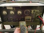
However, I am unable to move the main AC Breaker to the "ON" position. Attempting to do so you can visually see the spark of the trip through the clear rubber cover and hear the motor skip a step.
I can actually start the generator with the Main A/C Circuit Breaker in the "ON" position and it will stay there, but I will get the same ~0.2v reading on the convenience receptacles. The AC Volts and Hertz meters will read zero.
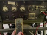
If I flip the Main A/C Circuit Breaker OFF, the AC Volts and Hertz meters will come to life and I get the proper voltage reading on the convenience receptacle. This behavior can be seen in this very short video I took:
I have performed all the trouble shooting that I could find in the TM 5-6115-615-12 - 062759 Operators & Maintenance Manual:
Section 3-3 Troubleshooting, #7 is "GENERATOR SUPPLIES NO VOLTAGE TO LOAD" but the instructions aren't very helpful as I am "higher echelon maintenance" for my poor generator. and I don't have anything connected yet, I am just trying to get 120V reading on each L1 & L2 (since I have it in the 120/240v single phase operation)


Section 3-35.5 instructs to inspect the Main Circuit breaker and connections. All connections on the back of the circuit breaker on the inside were very secure, and I could see no physical damage any other markings indicating an issue (melting, etc)

Section 4-2, part 8, instructs to check the load for a short circuit, but again, I don't have a load connected at all to it yet as I was just trying to get the voltage to read on the terminal/lugs first.

Finally, section 4-70 has me label each of the wires and remove the circuit breaker and test it, which I have done.
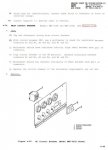
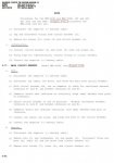
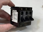
The side of the main circuit breaker reads:
72-169-2-MG6
__________P1P2_____P3
AMP _____35_______ 20
VOLT_____250______250
HZ______50/60____50/60
Delay______P________ P
Line
13208E5838-1
PAM333-MG6
I followed the above instructions and my results were as follows:
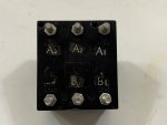
When the circuit breaker was in the "OFF" position, A1-B1, A2-B2, and A3-B3 showed higher resistance than my Fluke Multimeter could read (aka Open Circuit) (it was actually an open circuit between all the pins).
When the circuit breaker was in the "ON" position, A1-B1, A2-B2, and A3-B3 each read ~0.3-0.4 ohms, and open circuit between all others.
The TM says there should be a zero ohm reading between the pairs of pins (A1-B1, A2-B2, and A3-B3) when in the "ON" position. 0.3-0.4 ohms is not zero but it also is not very much resistance. Is the circuit breaker O.K. then or should it be replaced? I don't know what else to check.
(if needed, I do have 2 other MEP-701A generators that DO work as expected and I could borrow their Main Circuit Breaker)
Thank you very much!
My 1986 MEP-016B (with ~784 hours) starts and runs great, even after a long period of sitting.
I have my generator configured in the inside panel to be 120/240V Single Phase.
Voltage Selector on V1-0
Current Selector on I-2
If the Main A/C Circuit Breaker is in the "OFF" position, I get a voltage reading on the convenience receptacles that matches the panel "AC Volts" meter. I can adjust the voltage via the Voltage adjust knob and I can adjust the frequency displayed on the Hertz meter with the Manual Speed Adjustment knob. As expected with the Main AC Circuit Breaker in the "OFF" position, there is no voltage reading on the terminal/lugs on the right side (well, there is but it's only about 0.2V).

However, I am unable to move the main AC Breaker to the "ON" position. Attempting to do so you can visually see the spark of the trip through the clear rubber cover and hear the motor skip a step.
I can actually start the generator with the Main A/C Circuit Breaker in the "ON" position and it will stay there, but I will get the same ~0.2v reading on the convenience receptacles. The AC Volts and Hertz meters will read zero.

If I flip the Main A/C Circuit Breaker OFF, the AC Volts and Hertz meters will come to life and I get the proper voltage reading on the convenience receptacle. This behavior can be seen in this very short video I took:
I have performed all the trouble shooting that I could find in the TM 5-6115-615-12 - 062759 Operators & Maintenance Manual:
Section 3-3 Troubleshooting, #7 is "GENERATOR SUPPLIES NO VOLTAGE TO LOAD" but the instructions aren't very helpful as I am "higher echelon maintenance" for my poor generator. and I don't have anything connected yet, I am just trying to get 120V reading on each L1 & L2 (since I have it in the 120/240v single phase operation)


Section 3-35.5 instructs to inspect the Main Circuit breaker and connections. All connections on the back of the circuit breaker on the inside were very secure, and I could see no physical damage any other markings indicating an issue (melting, etc)

Section 4-2, part 8, instructs to check the load for a short circuit, but again, I don't have a load connected at all to it yet as I was just trying to get the voltage to read on the terminal/lugs first.

Finally, section 4-70 has me label each of the wires and remove the circuit breaker and test it, which I have done.


The side of the main circuit breaker reads:
72-169-2-MG6
__________P1P2_____P3
AMP _____35_______ 20
VOLT_____250______250
HZ______50/60____50/60
Delay______P________ P
Line
13208E5838-1
PAM333-MG6
I followed the above instructions and my results were as follows:
When the circuit breaker was in the "OFF" position, A1-B1, A2-B2, and A3-B3 showed higher resistance than my Fluke Multimeter could read (aka Open Circuit) (it was actually an open circuit between all the pins).
When the circuit breaker was in the "ON" position, A1-B1, A2-B2, and A3-B3 each read ~0.3-0.4 ohms, and open circuit between all others.
The TM says there should be a zero ohm reading between the pairs of pins (A1-B1, A2-B2, and A3-B3) when in the "ON" position. 0.3-0.4 ohms is not zero but it also is not very much resistance. Is the circuit breaker O.K. then or should it be replaced? I don't know what else to check.
(if needed, I do have 2 other MEP-701A generators that DO work as expected and I could borrow their Main Circuit Breaker)
Thank you very much!
Last edited:


