• Steel Soldiers now has a few new forums, read more about it at: New Munitions Forums!

  • Microsoft MSN, Live, Hotmail, Outlook email users may not be receiving emails. We are working to resolve this issue. Please add support@steelsoldiers.com to your trusted contacts.

MEP-802A voltage readings not right.

Guyfang

Moderator
Staff member
Moderator
16,701
23,937
113
Location
Burgkunstadt, Germany
I stand corrected. Just spoke with a friend, and he told me that the 400 hertz exciter stator is NOT compatible to the 60 hertz model. Look at figure 24, item 23. That is the part I mean.

Is this the test procedure you used?

5.2 Troubleshooting Guidelines
If the fuse blows perform the following tests:
a) Disconnect wire # 106B from A1, terminal 8; disconnect wire # 107B from A1, terminal 7.
b) Connect a digital multimeter, set to "ohms," between A1 terminal 7 and A1 terminal 8. Resistance value
should be high. Low resistance indicates a defective bridge rectifier circuit. Perform same test across A1
terminal 7 and A1 terminal 8 in "diode check" mode. Voltage drop should be approximately 1-1.2 VDC. A
zero (0) VDC reading indicates a defective bridge rectifier circuit. If the resistance reading is low or the
voltage reading is zero (0) the A1 must be replaced.
c) With wire #’s 106B and 107B still disconnected, connect digital multimeter, set to "ohms," between wire #
106B and wire # 107B.
d) Check the "Quad" winding for proper resistance (Re: TM 9-6115-641-24, Figure 4-10.7, steps h & i and
TM 9-6115-642-24, Figure 4-10.7, steps h & i) Reading should be 0.9 - 1.2 ohms for the MEP-802/803 and
1.2-1.6 ohms for the MEP 812/813. Verify resistance value does not drop during test. If reading is out of
tolerance the stator must be replaced
e) With "Quad" circuit still disconnected, test engine. If engine takes an excessive amount of time to start
or and/or an excessive amount of time to develop rated speed, troubleshoot the engine fuel system. Verify
that fuel system is free of contaminants. Verify condition of fuel filters. Verify correct operation of electric
fuel pumps. Verify combustion on all cylinders. Verify correct installation and adjustment of injection
pumps. Verify correct operation of injector nozzles. Repair or replace components as necessary.
f) Retest engine and verify correct operation
g) Verify correct readings on A1 and "Quad" winding.
h) Reconnect wire # 106B to A1 terminal 8; reconnect wire # 107B to A1 terminal 7.
i) Install new fuse
j) Test generator set
 

Saunders

New member
19
3
3
Location
Claremore, OK
I stand corrected. Just spoke with a friend, and he told me that the 400 hertz exciter stator is NOT compatible to the 60 hertz model. Look at figure 24, item 23. That is the part I mean.

Wondering if your manual is a newer version. From what I can tell the exciter stator should be item 10? Here's a link to the one I was using, page 222 of 293 in the pdf file or 4-27 on the page. http://www.liberatedmanuals.com/TM-9-6115-642-24.pdf

Is this the test procedure you used?

Our fuse wasn't blown so we didn't go that route. Is there another repair manual out there, the one I referenced didn't have a section 5.2.

5.2 Troubleshooting Guidelines
If the fuse blows perform the following tests:
a) Disconnect wire # 106B from A1, terminal 8; disconnect wire # 107B from A1, terminal 7.
b) Connect a digital multimeter, set to "ohms," between A1 terminal 7 and A1 terminal 8. Resistance value
should be high. Low resistance indicates a defective bridge rectifier circuit. Perform same test across A1
terminal 7 and A1 terminal 8 in "diode check" mode. Voltage drop should be approximately 1-1.2 VDC. A
zero (0) VDC reading indicates a defective bridge rectifier circuit. If the resistance reading is low or the
voltage reading is zero (0) the A1 must be replaced.
c) With wire #’s 106B and 107B still disconnected, connect digital multimeter, set to "ohms," between wire #
106B and wire # 107B.

I may have skipped some steps here, the section under Table 4-1 on determining resistant values at ambient temps reminded me of how long its been since high school calculus.

We simply disconnected the two wires from A1 regulator terminals 7&8 and checked ohm's between the two wires and got no reading at all, like an open circuit. I saw in table 4.1 it states resistance should be .9 to 1.2. Perhaps there is a broken wire which I'll check when I'm out there again. That's we're we left off. We need to verify some of these wires again and make sure nothing is broke or has been hooked up wrong.

d) Check the "Quad" winding for proper resistance (Re: TM 9-6115-641-24, Figure 4-10.7, steps h & i and
TM 9-6115-642-24, Figure 4-10.7, steps h & i) Reading should be 0.9 - 1.2 ohms for the MEP-802/803 and
1.2-1.6 ohms for the MEP 812/813. Verify resistance value does not drop during test. If reading is out of
tolerance the stator must be replaced
e) With "Quad" circuit still disconnected, test engine. If engine takes an excessive amount of time to start
or and/or an excessive amount of time to develop rated speed, troubleshoot the engine fuel system. Verify
that fuel system is free of contaminants. Verify condition of fuel filters. Verify correct operation of electric
fuel pumps. Verify combustion on all cylinders. Verify correct installation and adjustment of injection
pumps. Verify correct operation of injector nozzles. Repair or replace components as necessary.
f) Retest engine and verify correct operation
g) Verify correct readings on A1 and "Quad" winding.
h) Reconnect wire # 106B to A1 terminal 8; reconnect wire # 107B to A1 terminal 7.
i) Install new fuse
j) Test generator set
Thanks GuyFang again for taking the time to assist. I'm sure there are others who may be in this same boat and can benefit from your experience. Sometimes I have to read the same thing several times before it makes sense and sinks in. I'll post what we find when we get back out there. It's an hour and half drive one way, so time to work on it is limited.
 
Last edited:

Saunders

New member
19
3
3
Location
Claremore, OK
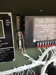
Finally got this problem figured out! Ended up being the quad mod fuse was bad. I previously checked between the two ends of the fuse and got continuity, so figured it was good. But, I made the careless mistake of not removed the fuse from the holder when I checked it. I was basically getting continuity from the rest of the circuit and not actually going thru the fuse. I should know better :(

I first checked pins 3&4 on the J5/P5 plug going to the generator and got 1.4 ohms. Manual says it should be between .9053 and 1.224, but my MEP-803A at home measures the same 1.4 too and works just fine. Anyways, figuring the quad winding was ok, I placed a jumper wire across the fuse since I didn't have one with me (voltage reg already checked out ok) and what do you know, 120 volts.

We still had the issue of the wires being connected up wrong between the S8 and K1 relay, perhaps that caused fuse to blow to begin with, who knows. Know a lot more now than I did before. Thanks again to everyone that helped me on this.

Can't help but think of that famous scene from the movie Sling-blade: https://www.youtube.com/watch?v=AynXoLjYrKc

Without checking the simple things first, we can quickly over analyze a situation.
 

Attachments

kloppk

Well-known member
Steel Soldiers Supporter
2,135
3,506
113
Location
Pepperell, Massachusetts
Just as a reminder for others reading this thread in the future.
NEVER temporarily bypass the QUAD Mod fuse with a jumper unless you are absolutely certain the the Voltage regulator is good.

Why? The primary purpose of the fuse is to protect the Quad winding from a shorted out voltage regulator. Should the regulator be shorted and you jump the fuse you will fry the Quad winding in the generator head.

(The OP knew his regulator was good so his jumping of the fuse was OK)
 
Last edited:
Top
AdBlock Detected

We get it, advertisements are annoying!

Sure, ad-blocking software does a great job at blocking ads, but it also blocks useful features of our website like our supporting vendors. Their ads help keep Steel Soldiers going. Please consider disabling your ad blockers for the site. Thanks!

I've Disabled AdBlock
No Thanks