• Steel Soldiers now has a few new forums, read more about it at: New Munitions Forums!

  • Microsoft MSN, Live, Hotmail, Outlook email users may not be receiving emails. We are working to resolve this issue. Please add support@steelsoldiers.com to your trusted contacts.

MEP-803a overload circuit

TNriverjet

Active member
Steel Soldiers Supporter
1,172
24
38
Location
Clifton, TN
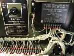
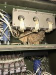
I will to unhook everything and take a look at connections on the K8. I did have a mouse nest under the transformer (since cleaned out), so I will check out the K8 to be sure there is no corrosion. I will also count wraps of wire. The -24 TM states 4 wraps. Mine appeared to have more wraps that that. Are the doubled and the count needs to be divided by 2?

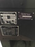
IMG_4258.jpgIMG_4220.jpg
 

jamawieb

Well-known member
1,437
556
113
Location
Ripley/TN
There is a connection board located under the old rat nest, make sure all those connections are tight and not corroded. Rat urine will cause serious corrosion. I had an 802a that had 1 loose connection on that board, that caused a O/L and almost melted the connector. Also spray the AM/VM switch on the front panel while turning it and make sure all those connections are tight. On the reconnection switch, make sure you are spraying from the bottom, sides and not just from the top.
 

Guyfang

Moderator
Staff member
Moderator
16,777
24,105
113
Location
Burgkunstadt, Germany
Take the time to unscrew the CT, and check that Mr. and Mrs. mouse did not remove some of the wire insulation from your load wires, or the TB below, to renovate their condo. It's a PITA, but there could be your problem.

Do not, unless you really have to, remove the 6 wires attached to the front of the CT. The studs can and will break off, sometime very easy.

I would say that the load wires look about right, but if you can check the wire numbers against the wire diagram, it will not be a bad thing. In fact, you have no idea what happened to this machine before you got it. That's why, if I disconnect ANY wires from ANY component, I would NOT mark the wires, or components. I WOULD get the wire diagrams out, and replace the wiring IAW the wire diagram. In theorie, your problem could be something miswired. If you reattach wires in the same order that you took them off, and don't check the wire diagram, you simply compound the problem. For me, everything in the gen set is suspect, until I che checked it out, or have seen the set work right.

When you rotate the S8, (and for that matter, S6), how does the switch feel? Smooth? Or hard, gritty? The S8 and S6 are of a switch type that allow dust and dirt to enter the switches, over long time periods.

I cant tell from the picture, but does your set have the quad circuit fuse, mounted next to the A1, AC volt regulator?

Oh, please take the time to remove the negative battery terminal before unhooking stuff, working with metal tools or hunting for Easter eggs. To the right of S6 for instance is MT4, (ammeter shunt) if you drop a wrench on it, you will be seeing spots before your eyes for a while. Safety First.
 
Last edited:

TNriverjet

Active member
Steel Soldiers Supporter
1,172
24
38
Location
Clifton, TN
When you rotate the S8, (and for that matter, S6), how does the switch feel? Smooth? Or hard, gritty? The S8 and S6 are of a switch type that allow dust and dirt to enter the switches, over long time periods.
I cant tell from the picture, but does your set have the quad circuit fuse, mounted next to the A1, AC volt regulator?
Oh, please take the time to remove the negative battery terminal before unhooking stuff, working with metal tools or hunting for Easter eggs. To the right of S6 for instance is MT4, (ammeter shunt) if you drop a wrench on it, you will be seeing spots before your eyes for a while. Safety First.
The switches feel smooth with positive engagement. I've sprayed them both with electrical contact cleaner. This flashes off pretty quickly and dries things out. I plan to pick up some "Deoxit" today which also has some some lubricating qualities.

I do have the quad circuit fuse added. See photos below. I should add this is a low hour (8 hrs, now has 15hrs) unit refurbished by Oregon RSMS in 2010. I do however agree that it still could be wired incorrectly.

IMG_4260.jpgIMG_4264.jpg

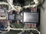
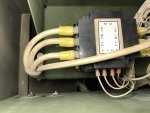
Here re are a few more pics of connections, etc

IMG_4261.jpgIMG_4263.jpgIMG_4262.jpg

Some of the stuff behind the front panel looks new. Thanks on the battery disconnect suggestion. I was under the impression shutting off the dead crank switch disconnected power. Yes, I know what "a&&"uming will get me...
 

jamawieb

Well-known member
1,437
556
113
Location
Ripley/TN
I still think you have a dirty connection causing the problem but you can also de-solder the burden resistors and check them with and ohm meter. They are part of the control circuitry but I've never had any go bad to show O/L. I've had a couple go bad that would set off the short circuit malfunction but not the overload.
 

TNriverjet

Active member
Steel Soldiers Supporter
1,172
24
38
Location
Clifton, TN
I still think you have a dirty connection causing the problem but you can also de-solder the burden resistors and check them with and ohm meter. They are part of the control circuitry but I've never had any go bad to show O/L. I've had a couple go bad that would set off the short circuit malfunction but not the overload.
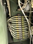
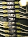
I did a bunch of disconnect/clean/reconnect on the K1 and TB3 yesterday. I also used a can of Deoxit D5 on both rotating switches while working them back and forth. Deoxit doesn't flash off as quickly as E/C cleaner, so I've let it sit overnight to "dry out" a bit. I plan to hook up a load and test later today. The connections on TB3 were a bit dirty, but tight and everything basically wiped off. I still used some emery cloth lightly on the base and connectors to make sure.

IMG_4265.jpg 41GI8hH77cL.jpg
 

TNriverjet

Active member
Steel Soldiers Supporter
1,172
24
38
Location
Clifton, TN
I ran a load test again Wed. It tripped the overload on anything over 50% (took 10-15 min), so something has improved. I was able to run 50% or less for over an hour before I had to shut down. I plan to dig deeper on cleaning and tightening connections. The load board is my next target. The lugs look brand new, so I'm wondering if all connections behind are good.
 

Guyfang

Moderator
Staff member
Moderator
16,777
24,105
113
Location
Burgkunstadt, Germany
Can you get a clamp on Amp meter? One that holds the highest reading? Then load it up, and measure each leg. See just what Amperage you are, drawing.

Is any carbon comming out of the exhaust? Does the exhaust smell funny. A bit oily, or like diesel? If so, load it to 30-40% and let it run 1-2 hours.
 

Dwnorton1

Member
Steel Soldiers Supporter
400
23
18
Location
Healdton Oklahoma/ SOOK
Sounds nice. We can start the baking cookies while load testing 803 club.:) I was doing night OPS in my pic. 42FLA with all burners on 34amps during cycles on burners.

IMG_0392 (1).jpg
 

CT-Mike

New member
238
2
0
Location
CT
Do you have a ground rod driven and connected when you are testing this using the stove? If not, I would highly recommend doing so to prevent possible serious injury or death. Just my $0.03 (adjusted for inflation).
 

CT-Mike

New member
238
2
0
Location
CT
Also remember as mentioned above the the heater elements in the stove are purely resistive, ie: pF = 1.0. These gensets are rated for a pF of 0.8, so you need to divide your indicated load by 0.8 to get true load.
 

Dwnorton1

Member
Steel Soldiers Supporter
400
23
18
Location
Healdton Oklahoma/ SOOK
Mike thanks for looking out for us. I would not consider running a load test without having unit and distribution grounded. That is very good advise. Ground fault with no path could result in very bad day. Also had neutral bonded to ground at gen. By my calcs the 42fla at 1PF is pretty close to max capacity of an 803. Might be able to squeeze 7 more amps inductive before approaching 125%. Didn't try it, but could probably get by with it. Would not believe the carbon sparkles that came out exhaust.

http://www.youtube.com/watch?v=q5b4vMBjjxQ
 

TNriverjet

Active member
Steel Soldiers Supporter
1,172
24
38
Location
Clifton, TN
Do you have a ground rod driven and connected when you are testing this using the stove? If not, I would highly recommend doing so to prevent possible serious injury or death. Just my $0.03 (adjusted for inflation).
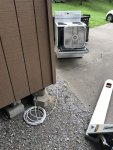
I do have an 8' ground rod near my load test area. I also have the neutral and ground bonded at the genset as is required for a stand alone system.
IMG_4252.jpg
 

Guyfang

Moderator
Staff member
Moderator
16,777
24,105
113
Location
Burgkunstadt, Germany
Mike thanks for looking out for us. I would not consider running a load test without having unit and distribution grounded. That is very good advise. Ground fault with no path could result in very bad day. Also had neutral bonded to ground at gen. By my calcs the 42fla at 1PF is pretty close to max capacity of an 803. Might be able to squeeze 7 more amps inductive before approaching 125%. Didn't try it, but could probably get by with it. Would not believe the carbon sparkles that came out exhaust.

http://www.youtube.com/watch?v=q5b4vMBjjxQ
Oh yes I would believe the carbon sparks! We set the woods on fire behind my shop in Kaiserslautern!!
 
Top
AdBlock Detected

We get it, advertisements are annoying!

Sure, ad-blocking software does a great job at blocking ads, but it also blocks useful features of our website like our supporting vendors. Their ads help keep Steel Soldiers going. Please consider disabling your ad blockers for the site. Thanks!

I've Disabled AdBlock
No Thanks