• Steel Soldiers now has a few new forums, read more about it at: New Munitions Forums!

  • Microsoft MSN, Live, Hotmail, Outlook email users may not be receiving emails. We are working to resolve this issue. Please add support@steelsoldiers.com to your trusted contacts.

MEP-803a overload circuit

TNriverjet

Active member
Steel Soldiers Supporter
1,172
24
38
Location
Clifton, TN
I was able to run another load test today. After start and warm up I progressively applied a 60% load. It ran fine for 12-15 min and then tripped the overload again. I reset everything and applied 50% load and it ran fine for the remaining 1:40. During the last 30-40 min I added a large burner on low. It would cycle on for 20-30 seconds and then remain off for 2-3 min. When on, it would step the load up to 75%, but wouldn't remain on long enough to trip O/L. This seemed to be a nice test and it handled the shifting loads fine. I'm still concerned that it won't take anything over 50% for a period of time without tripping. It should chug away with 60, 70, 80% or more.

Im feeling that thermal K1 O/L switch may be faulty. I'll have to read the TM to determine how it can be tested.
 

Another Ahab

Well-known member
17,999
4,556
113
Location
Alexandria, VA
I was able to run another load test today. After start and warm up I progressively applied a 60% load. It ran fine for 12-15 min and then tripped the overload again. I reset everything and applied 50% load and it ran fine for the remaining 1:40. During the last 30-40 min I added a large burner on low. It would cycle on for 20-30 seconds and then remain off for 2-3 min. When on, it would step the load up to 75%, but wouldn't remain on long enough to trip O/L. This seemed to be a nice test and it handled the shifting loads fine. I'm still concerned that it won't take anything over 50% for a period of time without tripping. It should chug away with 60, 70, 80% or more.
Shouldn't it "chug away" with up to 100% load, isn't that why it's rated like it is?
 

Guyfang

Moderator
Staff member
Moderator
16,778
24,105
113
Location
Burgkunstadt, Germany
K8 is the overload/short circuit relay. Test procedures for K8 are on page 2-58 of the -24 manual. I would also remove and open up K1.
 

TNriverjet

Active member
Steel Soldiers Supporter
1,172
24
38
Location
Clifton, TN
Shouldn't it "chug away" with up to 100% load, isn't that why it's rated like it is?
Yes, my 802a would nearly kill itself trying to stay online with a huge load. I had the resistance heat (emergency heat) try to come online once while the 802 was happily running the rest of the house.
 

TNriverjet

Active member
Steel Soldiers Supporter
1,172
24
38
Location
Clifton, TN
Ok, today I was able to run the test procedure for K8 from the -24 TM on page 2-58 and 2-59. All testing is conducted with the voltage reconnection switch in the 120/208 3P position.

There are essentially 6 tests to run in this procedure. The first 3 test operation/function of the OVERLOAD relay. There is one test per leg and testing is run on each of 3 phases.

The second set of 3 tests are run on the SHORT CIRCUIT relay. Again, each of the 3 phases are tested.

Here are my results:
Overload test one: O/L tripped in 9-10 seconds. (TM states this should take about 1 minute)
Overload test two: O/L tripped in 9 seconds (again 1m standard)
Overload test three: O/L tripped in 7 seconds (1m standard)
Interestingly the Hz readings were not consistent. The meter was reading about 56-57.5 Hz while I had the wires disconnected and tagged for testing

Short Circuit test one: immediate trip as per TM
Short Circuit test two: immediate trip as per TM
Short Circuit test three: immediate trip as per TM
Again, the Hz meter was not consistent when in test mode. Readings 57.5 - 60 Hz

The TM states if any of the above tests fail, the K8 relay needs replaced. Since the time factor is not clearly quantified, for the first series of three tests, I am not sure if this unit "passed" or "failed". Again the TM states, "After approximately one minute, AC circuit interrupter relay should open and OVERLOAD lamp should illuminate on malfunction indicator panel". It seems to me it is tripping too soon for this test, but the procedure did not say it had to endure 60 seconds to pass.

I'm planning to spend the remaining part of the afternoon taking K1 out and apart per Guyfang's recommendations.

Guyfang, did I get this sent out before bedtime Saturday?
 

Guyfang

Moderator
Staff member
Moderator
16,778
24,105
113
Location
Burgkunstadt, Germany
You just made the deadline! I was going to turn of the box, and decided to check ONE MORE TIME, and low and behold, you made it. It sounds to me like you may need a K8. Can you borrow one?
 

Guyfang

Moderator
Staff member
Moderator
16,778
24,105
113
Location
Burgkunstadt, Germany
You just made the deadline! I was going to turn of the box, and decided to check ONE MORE TIME, and low and behold, you made it. It sounds to me like you may need a K8. Can you borrow one?

Also, have you checked the Burden Resistors? R11, R12 and R13. The test procedure is in the book.
 

TNriverjet

Active member
Steel Soldiers Supporter
1,172
24
38
Location
Clifton, TN
I was just out there testing the burden resistors per the TM, but I can't get readings that make sense. I've read somewhere that they should really be un-soldered and tested for most accurate readings. However, the TM reads that they can be tested in place. To complicate things, I'm using an analog ohm meter that is older me, so I may need to go buy a good new digital amp clamp with test leads to get better readings. I did replace the batteries in my old meter and can now get more consistent readings.

I'll see if I can borrow a K8 from Jamawieb and work through taking apart and cleaning inside K1.
 

TNriverjet

Active member
Steel Soldiers Supporter
1,172
24
38
Location
Clifton, TN
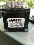
I just pulled K1, and may have found the problem... Shouldn't this be a 60 Hz??? See photo of tag on K1 rated at 400 Hz.
IMG_4317.jpg

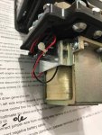
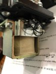
Also, here are photos of the inside...

IMG_4318.jpgIMG_4319.jpg
it's pretty clean. I haven't taken the Allen screws off the top yet, but am not sure I need to if this is a completely wrong part for an 803a. I'm wondering if this belongs in an 813a?
 

Haoleb

Member
197
6
18
Location
Raymond, Maine
It looks like the coil voltage for that contactor is 28VDC so nevermind the 400Hz spec. With a component like that the most important info is the coil voltage and the current rating. The reason it says 400Hz on the side is most likely because a contactor that was rated for up to 400Hz was needed.
 
Last edited:

jamawieb

Well-known member
1,437
556
113
Location
Ripley/TN
I was just out there testing the burden resistors per the TM, but I can't get readings that make sense. I've read somewhere that they should really be un-soldered and tested for most accurate readings. However, the TM reads that they can be tested in place. To complicate things, I'm using an analog ohm meter that is older me, so I may need to go buy a good new digital amp clamp with test leads to get better readings. I did replace the batteries in my old meter and can now get more consistent readings.
I'll see if I can borrow a K8 from Jamawieb and work through taking apart and cleaning inside K1.
You'll have to un-solder one side of the burden resistors. The TM does not say to but I can never get an accurate reading without un-soldering.

I may have an extra K8 I could send you for testing. I've never had a K8 fail, it is usually a burden resistor or dirty connection. First time for everything though.
 

Guyfang

Moderator
Staff member
Moderator
16,778
24,105
113
Location
Burgkunstadt, Germany
This would have been a good time to exercise your logistical talents. Look up the K1 to see if it has a UOC, Usable On Code, to determine if it is a 60 hertz, or 400 hertz part. You can learn a lot by reading. Haoleb is correct. Control voltage is DC, 28 volts. And the relay is rated for use with 50/60-400 hertz.

Agreed. K8 is normally a very robust part. Have only seen maybe two bad ones. Usual culprit is the resisters. But the K8 test procedures tend to point to the relay. My only problem with the test is that the relay still is in the set, and not disconnected from the burden resistors. Or am I wrong? I assume that the K8 test, requires the K8 to sense an overload, for 60 seconds, before it pops off. That's what happens in real life. It doesn't pop off as soon as it senses an overload. Yours does, after a few seconds.

And as jamaweib said, always un-solder at least one side to test the resisters. You will never get a trustworthy reading any other way. Do not use too much heat when you de-solder. The posts, that hold the resisters in, are plastic. If you overheat them, they tend to break.
 
Last edited:

Johncar48

Member
91
30
18
Location
Kerrville, tx
Yeh guys. I really enjoy reading and learning from you all. I'm pretty new here and just got my 803 all cleaned up and ready to wire into the house. However, I've read conflicting info about bonding the ground & neutral terminals when using the genset stationary. Your advice and knowledge would be greatly appreciated.
 

jamawieb

Well-known member
1,437
556
113
Location
Ripley/TN
Yeh guys. I really enjoy reading and learning from you all. I'm pretty new here and just got my 803 all cleaned up and ready to wire into the house. However, I've read conflicting info about bonding the ground & neutral terminals when using the genset stationary. Your advice and knowledge would be greatly appreciated.
This has been discussed and debated a bunch. If you're using 4 wire hookup to the house with an independent ground I would just unbound them. To be honest, I've never un-bonded the unit I set up at my parents house because I forgot when I first installed and never went back to redo.
 

Daybreak

2 Star Admiral
Steel Soldiers Supporter
1,522
771
113
Location
Va
Thanks very much for the reply. Think I will keep them bonded. Did you work on these units in the military?
Howdy,
In the middle of a field... bonded strap in place., and ground is connected to ground rod in the dirt.


Your house electrical panel, you have a proper ground in place. You are using the ground which was put in when the house was built.
Generator is connected with a 4 wire connection. Bond strap removed. All 4 wires connected, 2 hots, neutral, and ground. Again, you are using your house panel ground.
 

Johncar48

Member
91
30
18
Location
Kerrville, tx
Thanks Mike. Running 3 wires to house panel, 2 hots & a neutral. Panel is grounded. House is new but still under construction for I am building it myself. 2 a/c units (2 and 3 1/2 ton units) and lights produce about a 40% load factor but when demand hot water kicks in generator takes a dive south. Water heater rated at 4800 watts. Live in rural area so may need to switch to mep 003a which I just bought. 803 unit has 5200 hrs on it but is clean & runs well. 003 only has 1200 hrs on it but needs work. Have no idea when it was last run for fuel tank is missing, all filters have been removed & all fluids have been well drained. So it's a project. Appreciate the info & thanks for response.
 

Daybreak

2 Star Admiral
Steel Soldiers Supporter
1,522
771
113
Location
Va
Thanks Mike. Running 3 wires to house panel, 2 hots & a neutral. Panel is grounded. House is new but still under construction for I am building it myself. 2 a/c units (2 and 3 1/2 ton units) and lights produce about a 40% load factor but when demand hot water kicks in generator takes a dive south. Water heater rated at 4800 watts. Live in rural area so may need to switch to mep 003a which I just bought. 803 unit has 5200 hrs on it but is clean & runs well. 003 only has 1200 hrs on it but needs work. Have no idea when it was last run for fuel tank is missing, all filters have been removed & all fluids have been well drained. So it's a project. Appreciate the info & thanks for response.
Howdy,
You are missing the point.
4 wires connected between generator and panel. bonding strap removed.

Since you are still building...
Generator connection choices

Maybe your MEP-803A is not working at its peak performance.
Working MEP-803A 3kw to 16kw loading
 

TNriverjet

Active member
Steel Soldiers Supporter
1,172
24
38
Location
Clifton, TN
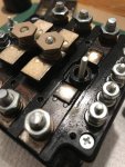
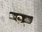
Ok, I took apart K1 today and cleaned the insides with deoxit. It really wasn't too bad and seemed to be making good contact. There were a few minor burns spots on the contacts, but were not charred. Here are photos:

IMG_4320.jpgIMG_4321.jpg
They look a lot darker in the photos than they did in person...

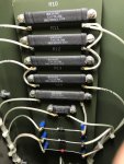
I will also be testing burden resistors per TM page 2-61 paragraph 2-43.2. I've ordered a newer more accurate "amp clamp" style tester that should arrive later this week, so I'll be getting these unsoldered next weekend for the test.
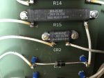
IMG_4322.jpgIMG_4324.jpg
Does R15 or CR2 look a little charred or is that just burnt insulation from soldering?
Does it matter which end of each resistor is unsoldered?
 
Top
AdBlock Detected

We get it, advertisements are annoying!

Sure, ad-blocking software does a great job at blocking ads, but it also blocks useful features of our website like our supporting vendors. Their ads help keep Steel Soldiers going. Please consider disabling your ad blockers for the site. Thanks!

I've Disabled AdBlock
No Thanks