• Steel Soldiers now has a few new forums, read more about it at: New Munitions Forums!

  • Microsoft MSN, Live, Hotmail, Outlook email users may not be receiving emails. We are working to resolve this issue. Please add support@steelsoldiers.com to your trusted contacts.

MEP-803a overload circuit

TNriverjet

Active member
Steel Soldiers Supporter
1,172
24
38
Location
Clifton, TN
I may have an extra K8 I could send you for testing. I've never had a K8 fail, it is usually a burden resistor or dirty connection. First time for everything though.
Thanks jamawieb, I may have found a K8, so I will keep you in mind if that falls through.
 

TNriverjet

Active member
Steel Soldiers Supporter
1,172
24
38
Location
Clifton, TN
This would have been a good time to exercise your logistical talents. Look up the K1 to see if it has a UOC, Usable On Code, to determine if it is a 60 hertz, or 400 hertz part. You can learn a lot by reading. Haoleb is correct. Control voltage is DC, 28 volts. And the relay is rated for use with 50/60-400 hertz.
Duly noted. Thanks for the UOC suggestion. I am still learning the lingo and sources for info!
Agreed. K8 is normally a very robust part. Have only seen maybe two bad ones. Usual culprit is the resisters. But the K8 test procedures tend to point to the relay. My only problem with the test is that the relay still is in the set, and not disconnected from the burden resistors. Or am I wrong? I assume that the K8 test, requires the K8 to sense an overload, for 60 seconds, before it pops off. That's what happens in real life. It doesn't pop off as soon as it senses an overload. Yours does, after a few seconds.
I'll get a good test on the resistors this coming weekend once my new meter arrives. If they pass, I should be ready for another load test before I move on to switching out the K8.
And as jamaweib said, always un-solder at least one side to test the resisters. You will never get a trustworthy reading any other way. Do not use too much heat when you de-solder. The posts, that hold the resisters in, are plastic. If you overheat them, they tend to break.
Any advice on which side of each to take loose? I will be extra careful... but may be shopping for new ones if my soldering technique is lacking. My solder gun is as old as the analog multi-meter I have... :doh:
 

jamawieb

Well-known member
1,437
556
113
Location
Ripley/TN
Ok, I took apart K1 today and cleaned the insides with deoxit. It really wasn't too bad and seemed to be making good contact. There were a few minor burns spots on the contacts, but were not charred. Here are photos:

View attachment 685697View attachment 685698
They look a lot darker in the photos than they did in person...

I will also be testing burden resistors per TM page 2-61 paragraph 2-43.2. I've ordered a newer more accurate "amp clamp" style tester that should arrive later this week, so I'll be getting these unsoldered next weekend for the test.
View attachment 685699View attachment 685700
Does R15 or CR2 look a little charred or is that just burnt insulation from soldering?
Does it matter which end of each resistor is unsoldered?
CR2 is just a diode so you can check that without unsoldering anything (but that doesn't have anything to do with K8). R10-R13 are the ones that lead to k8 and it's easier to just unsolder the left side on R10-R12, then you can test each one. R14 can be tested without de-soldering because it leads to the diode.
 

TNriverjet

Active member
Steel Soldiers Supporter
1,172
24
38
Location
Clifton, TN
Time for an update.

Received shipments from my auction site orders:
1. Spare K8
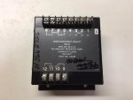
s-l1600-5.jpg

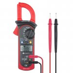
2. Better multi meter with amp clamp
s-l1600-6.jpg

3. NOS Weller Solder gun (new in box, but old model which had been sitting in an estate sale). Wow, it works great!
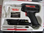
s-l1600-4.jpg

So to the generator...

In previous posts, I detailed removal and cleaning of K1. Last evening and today I performed burden resistor test by un-soldering and resistance testing. I also swapped the K8.
1. Burden resistors all tested out and were re-soldered with the new gun. Did I mention that thing works great compared to my 40 year old pencil type iron?[thumbzup]
2. Swapped K8 and set up for load test... same dismal results. O/L tripped after some time at higher loads.

I will say it seemed to run longer before tripping. The "floor" seemed to be closer to 60-65% of the load meter instead of 50%. However, the same result. I even reset everything and ran a second test ramped right up to 75% and then cycled a burner that took it up to 100% intermittently. It tripped within a few minutes on this test.

I'm thinking my K8 is fine and I now have a spare. I'm leaning towards a problem with the CT and/or the the wires that are wound through. I'll have to do some reading this week in the TM on test procedures for that component. Just thinking out loud here, could this still be an issue with K1???

Thanks in advance.
 

Guyfang

Moderator
Staff member
Moderator
16,766
24,074
113
Location
Burgkunstadt, Germany
Back about message 23? Or so, when you cleaned up TB3, did you check the wires against the wire diagram? Or just put them back on in the same way they came off?
 

TNriverjet

Active member
Steel Soldiers Supporter
1,172
24
38
Location
Clifton, TN
Back about message 23? Or so, when you cleaned up TB3, did you check the wires against the wire diagram? Or just put them back on in the same way they came off?
I put them back as I thought this was just a pass through block/attachment point. I guess the real question is if the correct wires are matched on either side! I think that will be my next item on the list to check. Any guidance on TM sections/pages for wiring diagram? Thank you.
 

novaman

New member
70
0
0
Location
michigan/Livonia
Same

Hey all ive got the same problem.o/l on a new mep803 i just got. I made the mep vs consumer gen video on YouTube 🤥. Ive been buying and selling these things when i can. Im well verse with electrical.
I went straight to the source. I volt metered out the ct. With a 10kw kiln wire element in front of a fan Im getting roughly 5v on 2 of the loops output sence windings and 10+volts on the 3rd winding. Output Voltage seams fine at the connection board. Thought it was the ct so i swapped it out with one from another unit. Same problem. Few minutes pass at 80% and o/l. I havent tested resistors or k8 yet but im thinking its a bad winding. Im going to ohm the windings tomorrow. I hope its a switch or resistor but i dont see how those could actually cause one leg to push more current then the other two. I think after 3 years of flipping i finally got my first parts unit. It was wet stacked too but just bearly starting to leak the black death around the manifold flange. Gave it a hot supper for like an hour before the first o/l trip cleaned it out a bunch but now every few minutes it pops. Also it wasnt reading proper on the load gauge. Like 30% with 48 amps on leg 1 and 3 had it in 120/240 setting. Put it in 3phase too but didnt use l2 and same same. My gut says its a bad winding mainly cause i paid $666 for this cursed thing 😈. Last thing to add to this novel it had a paper cecom reset team tag on it. Does that mean tier 2? Or was it suposed to end up there and never did sense it doesn't have any rivoted tier 2 tags. Or does it mean they just did a repair to it?
 
Last edited:

Guyfang

Moderator
Staff member
Moderator
16,766
24,074
113
Location
Burgkunstadt, Germany
An educated guess is that the tag ment the set needed to go to Reset. When reset is finished, NORMALLY, a tag is riveted onto the set. That doesn't mean it always happens.
 

Guyfang

Moderator
Staff member
Moderator
16,766
24,074
113
Location
Burgkunstadt, Germany
I put them back as I thought this was just a pass through block/attachment point. I guess the real question is if the correct wires are matched on either side! I think that will be my next item on the list to check. Any guidance on TM sections/pages for wiring diagram? Thank you.
Take a look at this file. It has some schematics and wire diagrams in it that are larger then normal. The wire diagrams show EACH component, and the wires that hook up to it, and where.


View attachment 10KW TQG Schematics[1].pdf
 

novaman

New member
70
0
0
Location
michigan/Livonia
Update

Update. Looks like it only over loads when its in 120/240 but not when in 3 phase... i cycled the switches a ton that did seam to make a difference on the load gauge. Gues ill check those resistors. In 3 phase Got 100% load on L1 and L3 runs fine all day. Put 100% on L1 and L2 runs fine all day. Put 100% on L2 and L3 runs fine all day. Put it into 120/240 single phase it cant handle 70% without poping from o/L.


K still havent checked resitors but heres more info. In 3 phase with a load from L1 to L3 the unit cannot maintain 208 from L1 to L3. L3 maintains 120v to N fine. L2 to N maintains 120 fine ( no load on that leg) but L1 drops to 110v to N.
In 120/240 voltage is constant with the load.
And when in 3 phase with load from L2 to L3 208v is fine however With nothing connected to L1 now voltage jumps to 125v!! From L1 to N ....WTF....
Lastly with an even 3 phase load from my nordic air 3ton ac / 9kw heater all the voltages are fine just when im only running a load on only 2 of the 3 legs does it get all SNAFU. seams more and more like a bad winding. Im going to check the resistors now.

Update
The resistors are all fine, the diodes are fine, didnt looke up the cap but its was like 800 something uf. Time to ohm the windings sad face

Update windings are fine!!! 0 ohms to there respective pair only. No continuity to ground. Happy day but.... WTF is it. Ill get some deoxit spray tomorrow and giver a bath.
First time i had to dig this deap to fix one but definatly addining to my resume of knowledge on these things.
 
Last edited:

Guyfang

Moderator
Staff member
Moderator
16,766
24,074
113
Location
Burgkunstadt, Germany
If you have checked the K8, and its good

If you have checked the windings and they are good

If you have checked the resistors, (please tell us what resistors) diodes and the caps, and they are good

And your deoxit doesn't do the trick

Then if I was you, I would disconnect every part of the system, and reassemble it BY the wire diagram.

Or change the S8.
 

jamawieb

Well-known member
1,437
556
113
Location
Ripley/TN
Sounds like s8 reconnection switch with corroded contacts. You have to work it left to right sometimes 100+ times while spraying electrical cleaner to clean the contacts. Usually if a winding is shorted, you wont get any output.
 

novaman

New member
70
0
0
Location
michigan/Livonia
If you have checked the K8, and its good

If you have checked the windings and they are good

If you have checked the resistors, (please tell us what resistors) diodes and the caps, and they are good

And your deoxit doesn't do the trick

Then if I was you, I would disconnect every part of the system, and reassemble it BY the wire diagram.

Or change the S8.
i checked all the burden resistors, diode and cap.
 

novaman

New member
70
0
0
Location
michigan/Livonia
Sounds like s8 reconnection switch with corroded contacts. You have to work it left to right sometimes 100+ times while spraying electrical cleaner to clean the contacts. Usually if a winding is shorted, you wont get any output.
Which Deoxit cleaner do I get there's like 7 kinds i found online cause no one seams to carry it locally or I suck at looking locally.
F5
D5
G5
D100
S5
R5
and
one that has no letter number combo maybe original blend
 

Haoleb

Member
197
6
18
Location
Raymond, Maine
The D5 stuff is what you want to get to spray into these switches.

Back in the day it was just Deoxit, then there was progold and faderlube all made by Caig labs. now it seems they call everything deoxit.
 
Top
AdBlock Detected

We get it, advertisements are annoying!

Sure, ad-blocking software does a great job at blocking ads, but it also blocks useful features of our website like our supporting vendors. Their ads help keep Steel Soldiers going. Please consider disabling your ad blockers for the site. Thanks!

I've Disabled AdBlock
No Thanks