• Steel Soldiers now has a few new forums, read more about it at: New Munitions Forums!

  • Microsoft MSN, Live, Hotmail, Outlook email users may not be receiving emails. We are working to resolve this issue. Please add support@steelsoldiers.com to your trusted contacts.

mep 803a power at lugs one time

Walter J Riedel

New member
20
4
3
Location
Harlingen, Texas
I am having an issue with power at lugs. New to me generator with 21 hrs on meter, no reset mod, 2005 year model. Professional wired to house. Started it and no power at lugs.
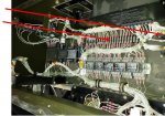
Opened unit and looked for loose wires . Found loose wire at K20. Started unit again and S5 switch worked and powered whole house for 4 hours. Days later no power when S5 raised. Have since read many threads and tested S5, K1. No issues. Found i have no power from S8 to K1 on B1 wire when running. There is power on all other terminals on S8. Should all B's have 110 when selector set to 120/240 single phase? Have used DeoxIT on S8 but still the same. Another issue is negative reading on ammeter. Tested alternator, output 47 volts. Have 50mv at back of gauge. Hope this information is enough to start.
 

csheath

Active member
714
213
43
Location
FL
Are you remembering to toggle the Circuit Interrupter switch closed after you start it?
 

kloppk

Well-known member
Steel Soldiers Supporter
2,149
3,536
113
Location
Pepperell, Massachusetts
Test the Contactor Closed Lamp to verify it's working. To do so put S1 in Prime/Run and press on the lamp lens to verify it illuminates.
With the set running and HOLDING S5 up does the contactor lamp illuminate?
 

kloppk

Well-known member
Steel Soldiers Supporter
2,149
3,536
113
Location
Pepperell, Massachusetts
I assume when you say "nothing" it means the contactor lamp did NOT illuminate.
So....

1) When you had the set running where there any Fault lamps illuminated. If unsure restart the set and verify no Fault lamps are illuminated. Are they all off?

2) Test the Fault Monitor by putting S1 in Prime Run and depress the TEST button on the Fault Monitor and verify all the lamps illuminate.

You'll need a hand held voltmeter to take some DC voltage measurements.
3) Open the gauge panel
4) Set you meter to DC volts
5) Connect your meters negative lead to the ground stud in the right corner of the gauge panel.
6) Start the generator
7) Measure the DC voltage at S5 terminals 2, 3 & 5. All three terminals should be ~ 24 volts DC. Are they?
8.) Measure the DC voltage at S5 terminal 6. It should be 0 volts DC. Is it?
9) Now connect your meters positive lead to S5-5.
10) While watching the meter lift S5 up and see if the DC voltage goes from ~24 volts DC to 0 volts DC when S5 is lifted UP. Does it?
 

Guyfang

Moderator
Staff member
Moderator
16,794
24,148
113
Location
Burgkunstadt, Germany
Before or after steps 7-10?

7) Measure the DC voltage at S5 terminals 2, 3 & 5. All three terminals should be ~ 24 volts DC. Are they?
8.) Measure the DC voltage at S5 terminal 6. It should be 0 volts DC. Is it?
9) Now connect your meters positive lead to S5-5.
10) While watching the meter lift S5 up and see if the DC voltage goes from ~24 volts DC to 0 volts DC when S5 is lifted UP. Does it?
 

kloppk

Well-known member
Steel Soldiers Supporter
2,149
3,536
113
Location
Pepperell, Massachusetts
If no 24 volts at S5-5 with the set running then there is a problem with the 24 volts getting from K20 the Oil Pressure relay all the way to S5-5.

Here is the path from K20-6 all the way to S5-5. With the set running start at K20-6 verify 24 volts DC is there and continue down the path until you lose 24 volts.

K20-6---Wire 150D---TB5-19---Wire150E---J6-29/P6-29---Wire 150B---K1-X-K1Coil-K1-Y---Wire152D---P6-35/J6-35---Wire 152C---TB5-16---Wire 152B---S5-5
 

kloppk

Well-known member
Steel Soldiers Supporter
2,149
3,536
113
Location
Pepperell, Massachusetts
Leave it plugged in and check all the other points along the path.
If what you get for measurements points to a P6/J6 problem then we'll need to do some resistance checks with the set OFF.
 

kloppk

Well-known member
Steel Soldiers Supporter
2,149
3,536
113
Location
Pepperell, Massachusetts
I you had 24 volts at K1-Y and nothing at TB5-16 then it could be a problem with the connection between P6 & J6.
With the set OFF and Dead Crank in OFF unplug P6 from J6. Access from the right door under the gauge panel.
You'll need to turn the locking collar on P6 CCW to unlock it before you can remove P6 from J6.

Examine the contacts in P6 & J6. Focus on pin 35. If no corrosion then you'll want to use you meter to check for continuity between K1-Y and P6-35. Then check for continuity between J6-35 and TB5-16.
 
Top
AdBlock Detected

We get it, advertisements are annoying!

Sure, ad-blocking software does a great job at blocking ads, but it also blocks useful features of our website like our supporting vendors. Their ads help keep Steel Soldiers going. Please consider disabling your ad blockers for the site. Thanks!

I've Disabled AdBlock
No Thanks