• Steel Soldiers now has a few new forums, read more about it at: New Munitions Forums!

  • Microsoft MSN, Live, Hotmail, Outlook email users may not be receiving emails. We are working to resolve this issue. Please add support@steelsoldiers.com to your trusted contacts.

MEP-805B Will not Start

jfpf6061

New member
26
1
0
Location
Brunswick, Ga
Hello,

I have an MEP-805b that we picked up from surplus that will not start unless I apply voltage to the actuator to engage. It will run and the governor light is on that states DC voltage. When the generator is running the speed sensor and actuator lights are not lit. I checked the magnetic pick up and it is fine and reading proper voltage in accordance with the TM. I have continuity at P5 on pins G and N to the MPU pickup wires. How do I test to see if the governor itself is bad or the board? I have read it could be the I/O Module too but I see no ways to test this. Can anyone please provide some help with this?

The only fault LED that is on is low CMOS voltage but I was told this should not affect this.

Thanks in advance.
 

Guyfang

Moderator
Staff member
Moderator
16,668
23,815
113
Location
Burgkunstadt, Germany
Hello,

I have an MEP-805b that we picked up from surplus that will not start unless I apply voltage to the actuator to engage. It will run and the governor light is on that states DC voltage. When the generator is running the speed sensor and actuator lights are not lit. I checked the magnetic pick up and it is fine and reading proper voltage in accordance with the TM. (with the two wires disconnected from the Mag pick up, and someone turning the set over with S1 or S10, the reading should be 2.5 to 3 volts, AC on the wire going to the Mag pickup. Is that what you got?) I have continuity at P5 on pins G and N to the MPU pickup wires. How do I test to see if the governor itself is bad or the board? I have read it could be the I/O Module too but I see no ways to test this. Can anyone please provide some help with this?

The only fault LED that is on is low CMOS voltage but I was told this should not affect this.

Thanks in advance.
.
 

Guyfang

Moderator
Staff member
Moderator
16,668
23,815
113
Location
Burgkunstadt, Germany
No!!! Between 2.5 and 3 volts. 3 is best!! No more, or the mag pickup is getting close to the flywheel teeth. But you need at LEAST 2.5 volts AC
 

jfpf6061

New member
26
1
0
Location
Brunswick, Ga
Okie dokie!! I’ll reset it tomorrow and see what happens and I’ll report back. I would love to get this working. Out of 10 surplus generators this one is the only problem we are having getting started. Thanks for the assist!!

Jim
 

155mm

Chief and Indian
Steel Soldiers Supporter
1,176
388
83
Location
Guymon, OK
my .02, I had 'one of those' also, she needed a new plug going to the actuator, the rubber spacers had fallen out and wouldnt maintain contact. I think that is the jenny that M35A2-AZ has now.

After the flywheel sensor is adjusted correctly, then look at the plug for the actuator.
 
Last edited:

baxter462

Member
79
2
8
Location
Salt Lake City Utah
AC voltage specifications in tech manuals are fairly useless for things like variable reluctance sensors unless you know what kind of volt meter the spec was originally developed for because the output of the sensor isn't a sine wave. If you're using a "true RMS" meter, and the spec was written for a non-RMS meter, or vice versa, your measurements won't match.

Guy, what meter do you use when you adjust them to 2.5v to 3v?
 
Last edited:

Guyfang

Moderator
Staff member
Moderator
16,668
23,815
113
Location
Burgkunstadt, Germany
I would have to go look. The army isn't into high speed, low drag meters, and that's what I use, Ex army meters. I think I have 4-5, (at least) and some are Fluke, one is from Blue Point, (snap on knock off) and at least one is some no name, cheap crap meter. BUT, very robust!! It fell off a three story roof, and still works! When it stop raining maybe I will look. Hasn't rained in over 6 weeks, and I am sitting here in my motorcycle gear, wanting to go out with a buddy, to Bamberg.
 

jfpf6061

New member
26
1
0
Location
Brunswick, Ga
Good morning,

I adjusted to 3 volts with my Fluke meter. The speed sensor light on the governor is now flashing while cranking. No actuator light.

Jim
 
Last edited:

baxter462

Member
79
2
8
Location
Salt Lake City Utah
According to the TM, if the speed sensor light flashes while cranking, but the actuator light doesn't come on, and the overspeed light isn't on, the speed control module needs to be replaced. I suppose you could try performing the overspeed reset procedure to see if it helps. Maybe the overspeed light has failed, but it is being commanded on? That's probably a long shot.

Before I replace any expensive electronic parts, I always check and clean all the connections. Poor terminal tension and corrosion cause all sorts of issues. I'd pull the speed control module off the back plane, inspect the connector, clean with DeOxIt, put it back together and retest. I'd probably do the same thing with all the modules that connect to the backplane, and maybe even put some no-ox or similar in the connectors upon reassembly. Make sure to take ESD discharge precautions during the process.

155mm, didn't you have an 805B that had strange issues that were miraculously fixed after you removed the backplane, inspected it, didn't find anything wrong, and reassembled? Dang microscopic corrosion on connector terminals.
 

155mm

Chief and Indian
Steel Soldiers Supporter
1,176
388
83
Location
Guymon, OK
I just cycled thru mine watching the light inside the cabin, and the actuator light does not light if you forget to push the fault reset button. I fubu'ed on that myself this morning, so that might be something else to look at.

Master on, wait for cim to boot, rotary switch to prime run, then push fault reset then start.

In the video, you can see i reset before turning switch to run, jenny failed to start.

https://youtu.be/U-RWshepFRk

Did you look at the wire connector on the actuator?

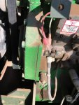
181DDBF1-007D-4697-9AB7-ADF576FDF79A.jpg
 
Last edited:

baxter462

Member
79
2
8
Location
Salt Lake City Utah
Good observation about the actuator light not coming on until the fault reset switch has been activated. I have started my 805B so many times that I don't even think about the procedure and sequence anymore. Good reminder.
 

155mm

Chief and Indian
Steel Soldiers Supporter
1,176
388
83
Location
Guymon, OK
Good observation about the actuator light not coming on until the fault reset switch has been activated. I have started my 805B so many times that I don't even think about the procedure and sequence anymore. Good reminder.
I normally have to hit the fault reset 2 times, because I have done it backwards since I started working on them, I added the start video to reply, I even do it wrong on the video, but it wont wear out that switch any faster having to click it twice
 

155mm

Chief and Indian
Steel Soldiers Supporter
1,176
388
83
Location
Guymon, OK
I wired both of mine white to white, then whatever the other is together.

EDIT

I was mistaken on what you were asking for.

White wire, 14v on start, 10.2v on run
Red/black, 0v on start, .2v on run

All measurements with black to ground on actuator, not to block or battery.

I am assuming on the next statement, I dont think it ground thru the body since it is filled with fuel under normal operations. I will bet that white is hot, and red/black is ground.

Attached is the manual for just the actuator that you are looking to operate manually.

https://www.steelsoldiers.com/showt...fuel-cutoff-tm-troubleshooting-install-manual
 
Last edited:

155mm

Chief and Indian
Steel Soldiers Supporter
1,176
388
83
Location
Guymon, OK
Hi,

Thanks. I have done that. On my pigtail to the actuator which wire should be hot when cranking to actuate and start and then holdout?
What did you do? replace the connectors on the actuator wires? or read thru the thread on my ginger jenny? or push the reset button after the switch is in the start run position?
 

baxter462

Member
79
2
8
Location
Salt Lake City Utah
I doubt the polarity matters. Neither wire has continuity to the housing of the actuator, and unless there is a clamping diode across the coil, it won't care what direction the current is.
 

155mm

Chief and Indian
Steel Soldiers Supporter
1,176
388
83
Location
Guymon, OK
I doubt the polarity matters. Neither wire has continuity to the housing of the actuator, and unless there is a clamping diode across the coil, it won't care what direction the current is.
Manual also stated .. to troubleshoot, measure resistance across both wires, so yep, one is hot and one is not.... swings both ways so it doesnt matter which wire goes where.
 

jfpf6061

New member
26
1
0
Location
Brunswick, Ga
What did you do? replace the connectors on the actuator wires? or read thru the thread on my ginger jenny? or push the reset button after the switch is in the start run position?
No, just making sure I read everything correctly. I have no voltage on cranking. I know I have continuity through everything that should from pin to terminal ends. Screens work as should. Overpeed light lights and resets. Faults clear and starting procedure is correct as indicated to me in the previous posts.

I can get the generator to start when I disconnect the terminal at the actuator and run hot to the white wire and ground the red. When I do that with the governor actuator locked down I overspeed and can reset but continues to overspeed.

I can untie the governor and run it and will not overspeed but I cannot flash field. The field flash relay opens and closes when I attempt to flash the field but it will not produce any voltage. I assume to the best of my limited knowledge it is because I have the actuator disconnected.

Everything I have done leads me to believe the governor is defective unless I am doing something totally wrong here.

Thanks for the assist and any advice is greatly appreciated.

Jim
 
Top