• Steel Soldiers now has a few new forums, read more about it at: New Munitions Forums!

  • Microsoft MSN, Live, Hotmail, Outlook email users may not be receiving emails. We are working to resolve this issue. Please add support@steelsoldiers.com to your trusted contacts.

MEP-831a Troubleshooting

nosliwwt

New member
5
0
1
Location
Wasilla, AK
Dewie38, 3800 RPM, does that run around 315 Hz?
Kloppk, went through your suggestion, ~202 Hz on A-B
27VDC on G-F
0-.33VDC D-E.

After awhile it intermittently stops responding to shutoff cues, IE E-Stop button and the start-run-stop switch. Wiring test are good.
I switched the governor actuator with one from a good genset and same response. If I flip the switch to stop and then back to run, the actuator sets the engine to 300+Hz and will then respond to shutdown cues. Also, I can then load test the set with minimal issues, a couple times it shut down for "low fuel pressure" (the filter was changed after the first occurrence).
 

kloppk

Well-known member
Steel Soldiers Supporter
2,145
3,526
113
Location
Pepperell, Massachusetts
...Kloppk, went through your suggestion, ~202 Hz on A-B...
I assume when you measured ~202 Hz was the engine RPM much lower?

When it stops responding to STOP is the engine RPM kinda low or still at a high RPM?

Are there any Fault lights on when it stops responding to STOP?

The Low Fuel fault is normally due to the fuel tank being virtually empty (or a bad/stuck float switch). It's not technically "Low Fuel Pressure".

. If I flip the switch to stop and then back to run, the actuator sets the engine to 300+Hz and will then respond to shutdown cues....
Before doing this is the engine RPM low and then rev up to ~300 Hz after you flip the switch??

3800 RPM would be ~318 Hz
 
Last edited:

nosliwwt

New member
5
0
1
Location
Wasilla, AK
Yes, the engine RPM is much lower, enough that when you attempt to close the contactor for power it will not light up. So I'm guessing the inverter recognizes this and will not close the circuit due to low RPM, low voltage.
RPM is low when it refuses to respond to shut off cues. No fault lights are lit, they all test good.
Low fuel isn't an issue, full tank of JP8, I haven't let it drop below a half tank.
Oil level is good and clean, 0W-30

And yes, before flipping the switch the engine RPM is low and then it revs up. If I move the throttle and bring it up to 318 Hz, the engine will sputter and backfire, kick out some white smoke. So maybe I have the valves too tight for the engine (adjusted to book specs), or my injector needs to be rebuilt?
The Governor actuator is fully open and the engine throttle lever is 1/4 below it, so the actuator is no longer managing the engine speed.
I'll figure out how transfer some pictures onto here if needed. This thing has had many new soldiers work on it, so there's little telling what's been done to it.
 

kloppk

Well-known member
Steel Soldiers Supporter
2,145
3,526
113
Location
Pepperell, Massachusetts
When it's at a low RPM and won't respond to a STOP is the LED in the K12 relay illuminated?
When illuminated it indicates there is a Fault and power has been removed from the A5 Governor Controller.
When this happens using the E-Stop or Run/STOP switch will have no affect on shutting down the set.

For a normally functioning set shutdown depends on DC power being removed from the Governor Controller when RUN/STOP is moved to STOP.
When power is removed the Governor Controller the actuator should swing back and be captured by the magnet causing the set to shut down.
This is due to the applied actuator force that's offsetting the mechanical governors force is being suddenly removed causing it to swing back and be captured by the magnet.

It's possible both Governor Controllers are bad.
The voltage at terminals G-F is correct.
The voltage at terminals D-E seems a bit off. I assume the 0.33 VDC was at no load? Normally this would correspond to about a 6% load or 200 watts.
At no load this should be 0.0 VDC and 5.0 VDC at full load.

At high RPM what is the DC voltage across terminals H-J on the Governor controller?
At high RPM what is the DC voltage across D-E?
 
Last edited:

nosliwwt

New member
5
0
1
Location
Wasilla, AK
Low RPM, the green light is illuminated on K12 relay. reset the power switch (without killing the genset) and the light goes out for K12, Illuminates the red light for K15.
At both High and low RPM, terminals D-E show ~.046 VDC, At High RPM the voltage varies with the load 0-3KW = .046 VDC - 5 VDC. So a normal reading.
No variation in RPM.
High RPM, H-J gives me battery voltage, 28 VDC.

I'll be out in PA for 6 weeks, so it'll probably just sit in my bay until I get back to work on it.

Hate to think the controllers are bad, that makes 3. One is fresh out of the box. Is there a test for those controllers listed anywhere?

Also, the low voltage reading may just be the multimeter giving a nominal reading
 
Last edited:

kloppk

Well-known member
Steel Soldiers Supporter
2,145
3,526
113
Location
Pepperell, Massachusetts
Low RPM, the green light is illuminated on K12 relay. reset the power switch (without killing the genset) and the light goes out for K12, Illuminates the red light for K15.
K12 LED on indicates the 831's fault system detected a fault and removed power from the Governor Controller and hence the actuator resulting in low RPM. Without power to the actuator the voltage at H-J will be 0 VDC.
Resetting the power switch clears the fault restoring power to the Governor Controller.
At both High and low RPM, terminals D-E show ~.046 VDC, At High RPM the voltage varies with the load 0-3KW = .046 VDC - 5 VDC. So a normal reading.
The readings you are getting across D-E is exactly right.

High RPM, H-J gives me battery voltage, 28 VDC.
That's not right. 28 volts will cause the actuator (throttle) to go to wide open throttle.
Should never see that situation in normal operation.
Under full load the voltage across H-J should only be ~11 VDC.

All your input voltages look right. The problem is the output H-J to the Actuator.
Tells me either the Controllers are bad or possibly way out of adjustment.

The only Controller "test" is what's in the -13 TM. Simply checking the input & output voltages at the controller.
There is a typo in the TM about this test as it state the voltage across D-E under full load. TM states 0 VDC and it should say 5 VDC as you already know.
 
Last edited:

nosliwwt

New member
5
0
1
Location
Wasilla, AK
I'll put this thing back under a load and see if I can get it to adjust down.

This still leaves my initial concern about the set starting in a faulted mode, but maybe this will resolve once it's in adjustment.
Will order another SLC through the system and see if that changes things, and of course get back to you on the results.

Thank you
 

Tango Zulu

New member
26
1
3
Location
SEFL
I have two units.

On unit A I can adjust the speed pot but the stab and gain don't do anything. On applying load the rpm will fall.

The other one, unit B, works perfectly but it reads ~55 VAC at idle. It is a newer unit but the controller is still a SLC1000. Are there controllers that read that VAC number at idle?

@kloppk - The controllers you sell: are they plug and play meaning there are no potentiometers to be adjusted at all?

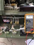
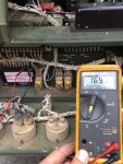
IMG_0961.jpgIMG_0963.jpg
 
Last edited:

kloppk

Well-known member
Steel Soldiers Supporter
2,145
3,526
113
Location
Pepperell, Massachusetts
Sounds like unit A may have a bad controller if adjusting Stability & Gain don't do anything.

The VAC across terminals A & B on the controller should be ~176 VAC, or approximately 254 Hz (3050 rpm) at no load when adjusted properly.

Correct, my controllers have no adjustments. Just install and run.

Per the TM the actuator linkage rod length should be adkusted so that the gap between the magnet and the target is 5/16” and no load (3050 RPM)
 

Tango Zulu

New member
26
1
3
Location
SEFL
Thanks.
Yes on Unit A the controller is probably kapputt. But on B like I said the unit works perfectly. I have applied 3KW loads for extended periods and there is nothing wrong with it at all. It just reads about 55 VAC at idle. No idea why.
 

Cord

Member
129
5
18
Location
Wisconsin
You wont find that info anywhere it is factory set. I know this because I helped develop this set, and I wrote the procedure for setting this governing system.
To properly set the pull off weight you need to disconnect the actuator rod from the actuator, and you would need a pull scale to measure the weight.
In any case I will send you the procedure when I find it.
Dewie, I replaced my controller and now need to reset the magnet so the gap can be properly set. By chance, did you ever find the magnet adjustment procedure?
 

DieselAddict

Well-known member
Steel Soldiers Supporter
2,532
2,059
113
Location
Efland, NC
Dewie, I replaced my controller and now need to reset the magnet so the gap can be properly set. By chance, did you ever find the magnet adjustment procedure?
Its pretty simple. You use a spring scale and adjust the magnet to get a pull-off force of 4 lbs +\- 0.25 lbs.

disconnect the governor rod from the governor bracket and use that hole to connect the scale.
 

DieselAddict

Well-known member
Steel Soldiers Supporter
2,532
2,059
113
Location
Efland, NC
You can't change the breaker to the factory outlet. The wiring inside won't handle that much power. You will want to install an outlet on the main lugs of the generator.

I'll be happy to help with the generator.

Looks like you are only about an hour away if you want to drag it over to Efland.
 

DieselAddict

Well-known member
Steel Soldiers Supporter
2,532
2,059
113
Location
Efland, NC
No. you can not do that. The internal wiring can not support more than 10 amps. You will set it on fire.
 

OverkillTASF

Member
92
6
8
Location
Central Virginia
I need to know if I can replace the breaker with a 15 amp or 20 amp instead?
Marcello, the generator itself can handle quite a bit more power, but that outlet, and the wiring to it, is a 15 amp outlet. It's a "convenience" outlet. That is not where you should be drawing the bulk of your power. Down at the bottom on the same side are the main lugs DieselAddict mentions... With the right cabling you can have a variety of hookups including an actual 20 amp outlet, or a 30 amp outlet. But those lugs are NOT on a breaker, so to do so safely requires some power protection between the lugs and your outlet that you install. With a little more detail about what you'd like to do we can draw something up for ya' on what you'd need to do it safely.
 
Top
AdBlock Detected

We get it, advertisements are annoying!

Sure, ad-blocking software does a great job at blocking ads, but it also blocks useful features of our website like our supporting vendors. Their ads help keep Steel Soldiers going. Please consider disabling your ad blockers for the site. Thanks!

I've Disabled AdBlock
No Thanks