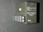
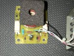
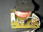
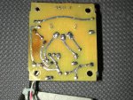
Maybe "We" can fix it??
Okay, I have been trying to figure out what to do.
I pulled the freq transducer out of my other 016B and put it on the bench and hooked up the original meter from the unit that was acting funny. The meter worked fine and exhibited no drift. Conclusion, bad transducer, as you all correctly predicted.
Found a new unit on line from Welscher instruments. 1% accuracy, 0 - 1mA output, 10K ohms. So that would work with the 1K resistor across the gage terminals. Only 1 problem, or maybe 2. The case is much larger. Biggest problem is $525.00 - OUCH

Also waiting on a reply from Delks.
Swaped the good transducer into my gen and ran it tonight - Perfect, no issues. While it was running I disassembled the defective one started looking at it.
This is a very simple device of what appears to be all resistors and capacitors, or maybe some of those are diodes?? (It does output DC with AC input.)
One of the large rectangular ceramic 5K resistors looked like it was putting heat to the board under it. Maybe that is all that is wrong?? See pics. Not super bad but discolored.
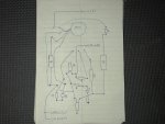
I made a wiring diagram (taken from the back side solder tracks) and have some pics.
I also thought about the possibility of installing a gas engine tachometer in the existing location and pulling a signal off of the 120vac somehow. Maybe a cheap solution to retain an analog gage and not modify the opening.
I would like to take a shot at fixing this simple board by replacing the defective component.
Any ideas where to start??? I was thinking of the resistor. What other components would cause the drift?? Capacitors?
Looking forward to some commments from the experts!!

