• Steel Soldiers now has a few new forums, read more about it at: New Munitions Forums!

  • Microsoft MSN, Live, Hotmail, Outlook email users may not be receiving emails. We are working to resolve this issue. Please add support@steelsoldiers.com to your trusted contacts.

mep002 FVR 4006 Regulator Source?

David Sims

New member
53
0
0
Location
Middle Georgia
When my genset batts sparked when I hooked up the batts I went and pulled off the capacitor because from reading past post the sparking was bad only to find out recently that it was suppose to do that ( thanks PeterD ) however my capacitor is still disconnected and my genset DC system is still charging. I also noted that on the civie Onan 10djc genset there is no part listing for a capacitor so I'm still curious to how inportant it is to have one

On edit I meant "Thanks PeterD":doh:
Bill W, I was under the impression (and hopeing) that the capacitor was needed for the Voltage Regulator to operate properly. I might be barking up the wrong tree?
 

Speddmon

Blind squirrel rehabiltator
Super Moderator
Steel Soldiers Supporter
4,640
28
38
Location
Cambridge, Ohio
you don't need it for the VR to operate properly, it is just there to protect it from any noise that may be induced into the system from the generator. You could probably run without it, but you may be severely shortening the life of the voltage regulator if you do
 

David Sims

New member
53
0
0
Location
Middle Georgia
Update

I installed the new capaciter this weekend. Still no charge. Tried a second one. No change. Removed the red banded wire with the unit running and got 7 or 8 ac volts.

So I was at a complete dead end and did what any logical person would do.
I got another MEP 002 that has a working charging system. 2700 hours and is not a looker but its all there and after 10 hours of running the shop I'm satisfied.

I removed the Voltage Regulator from the 2700 hr unit and put it on the 50 hour "no charge" machine and still got 7 or 8 volts with the red banded white wire removed. Remove the neg. batt post while the machine is running and it dies. Even though my stator tested good numerous times by the book I wonder if it's the problem?

Then I took the original V.R. from the 50 hr "no charge" and put it on the other and it's charging just fine. Remove the neg. batt and she keeps running. Remove the red banded wire and I got 30.8 ac volts.

Any hoo thanks to everyone that contributed to this. It's been a good learning experience. Tom Badgett at Gulf Coast Trucks really stuck with me as well. Don't know how many times I called him. He offered a refund and even offered to buy my original Voltage Regulator if it were to test good.

I'm thinking I'll get an external 24 v charger.

Thanks again,

David
 

Polycop

Member
65
1
8
Location
Nothern Indiana
Be careful running it without the batteries hooked up. I remember one poster saying he fried his charging system by running it without the batteries (or slave cable) hooked up.
 

Speddmon

Blind squirrel rehabiltator
Super Moderator
Steel Soldiers Supporter
4,640
28
38
Location
Cambridge, Ohio
I removed the Voltage Regulator from the 2700 hr unit and put it on the 50 hour "no charge" machine and still got 7 or 8 volts with the red banded white wire removed. Remove the neg. batt post while the machine is running and it dies. Even though my stator tested good numerous times by the book I wonder if it's the problem?

David
I see that in an earlier post you did re-test the stator output, and had about 33 volts (33.2 to be exact). The stator is good.

I am a bit confused as to why you keep stating all of these meter readings you get at the fuse holder and at the red marked wire on the VR as being ac volts. All of those places you should be reading DC volts. The only place you should see any ac voltage readings will be on the two wires coming from the stator. The readings you are getting on the DC side with your meter set on ac are probably just transient readings and do us no good to help you troubleshoot the problem.

When you said your machine is shutting down, was that with the known good VR from the 2700 hour machine on it? If it was then I think you have a bad wire somewhere. The batteries should not effect the machine running at all. When you remove the negative, obviously the fuel pumps are stopping and probably the fuel cut out solenoid may be dropping out because they no longer have a complete path for the 24 volts they need because they are running off of the batteries and not the charging system like they should be..

This tells me that the positive and ground paths are good to the batteries, but the 24 volt path between the DC VR and the batteries is no good. The VR should ground to the frame, so unless it's got an extremely bad ground it should be ok, but check it anyway. I would start by hooking everything up properly, and leave the machine off (not running). Have a good fuse in the fuse holder, and check for 24 volts DC at the red marked wire of the DC VR to the VR ground. Even though the set is not running, electrically that wire is still directly connected to the batteries and you should read 24 volts from the batteries. From what you are saying I'm wiling to bet you don't get 24 volts at that wire, I could be wrong though.

If you don't get 24 volts then you need to follow that wire the whole way to the batteries ( or where ever it goes, I'm not sure of the exact path of that wire) and find where you are loosing the voltage. Start with the fuse holder (both sides) checking to ground and at every junction or splice in that wire until you start getting 24 volts...once you find the 24 volts then you'll know where you are loosing it at (between the point where you find it and the next point toward the VR where you didn't have it). Fix that problem and I'll bet you get your charging system back.
 

Speddmon

Blind squirrel rehabiltator
Super Moderator
Steel Soldiers Supporter
4,640
28
38
Location
Cambridge, Ohio
Be careful running it without the batteries hooked up. I remember one poster saying he fried his charging system by running it without the batteries (or slave cable) hooked up.

Yes, that is bad for the charging system, but it is also an indication that the charging system is working. When he removes the negative cable and the machine shuts off, that means it is not charging, so it doesn't matter in that case (mostly because the machine shuts down and won't run...LOL).
 

David Sims

New member
53
0
0
Location
Middle Georgia
I see that in an earlier post you did re-test the stator output, and had about 33 volts (33.2 to be exact). The stator is good.

I am a bit confused as to why you keep stating all of these meter readings you get at the fuse holder and at the red marked wire on the VR as being ac volts. All of those places you should be reading DC volts. The only place you should see any ac voltage readings will be on the two wires coming from the stator. The readings you are getting on the DC side with your meter set on ac are probably just transient readings and do us no good to help you troubleshoot the problem.

AC listed due to my lack of experience on this. A retest is in order.
When you said your machine is shutting down, was that with the known good VR from the 2700 hour machine on it? Yes

If it was then I think you have a bad wire somewhere. The batteries should not effect the machine running at all. When you remove the negative, obviously the fuel pumps are stopping and probably the fuel cut out solenoid may be dropping out because they no longer have a complete path for the 24 volts they need because they are running off of the batteries and not the charging system like they should be..

This tells me that the positive and ground paths are good to the batteries, but the 24 volt path between the DC VR and the batteries is no good. The VR should ground to the frame, so unless it's got an extremely bad ground it should be ok, but check it anyway. I would start by hooking everything up properly, and leave the machine off (not running). Have a good fuse in the fuse holder, and check for 24 volts DC at the red marked wire of the DC VR to the VR ground. Even though the set is not running, electrically that wire is still directly connected to the batteries and you should read 24 volts from the batteries. From what you are saying I'm wiling to bet you don't get 24 volts at that wire, I could be wrong though.

If you don't get 24 volts then you need to follow that wire the whole way to the batteries ( or where ever it goes, I'm not sure of the exact path of that wire) and find where you are loosing the voltage. Start with the fuse holder (both sides) checking to ground and at every junction or splice in that wire until you start getting 24 volts...once you find the 24 volts then you'll know where you are loosing it at (between the point where you find it and the next point toward the VR where you didn't have it). Fix that problem and I'll bet you get your charging system back.
I appreciate the ideas. To be continued this weekend... Thanks.
 

David Sims

New member
53
0
0
Location
Middle Georgia
retested

I had a chance to re-test today. Results from today are in this color below:

I appreciate the ideas. To be continued this weekend... Thanks.
I see that in an earlier post you did re-test the stator output, and had about 33 volts (33.2 to be exact). The stator is good.

I am a bit confused as to why you keep stating all of these meter readings you get at the fuse holder and at the red marked wire on the VR as being ac volts. All of those places you should be reading DC volts. The only place you should see any ac voltage readings will be on the two wires coming from the stator. The readings you are getting on the DC side with your meter set on ac are probably just transient readings and do us no good to help you troubleshoot the problem.

When you said your machine is shutting down, was that with the known good VR from the 2700 hour machine on it? Yes. If it was then I think you have a bad wire somewhere. The batteries should not effect the machine running at all. When you remove the negative, obviously the fuel pumps are stopping and probably the fuel cut out solenoid may be dropping out because they no longer have a complete path for the 24 volts they need because they are running off of the batteries and not the charging system like they should be..

This tells me that the positive and ground paths are good to the batteries, but the 24 volt path between the DC VR and the batteries is no good. The VR should ground to the frame, so unless it's got an extremely bad ground it should be ok, but check it anyway. I would start by hooking everything up properly, and leave the machine off (not running). Have a good fuse in the fuse holder, and check for 24 volts DC at the red marked wire of the DC VR to the VR ground. I followed the above and it had 24.4volts DC at the red wire. Even though the set is not running, electrically that wire is still directly connected to the batteries and you should read 24 volts from the batteries. From what you are saying I'm wiling to bet you don't get 24 volts at that wire, I could be wrong though.

If you don't get 24 volts then you need to follow that wire the whole way to the batteries ( or where ever it goes, I'm not sure of the exact path of that wire) and find where you are loosing the voltage. Start with the fuse holder (both sides) checking to ground and at every junction or splice in that wire until you start getting 24 volts...once you find the 24 volts then you'll know where you are loosing it at (between the point where you find it and the next point toward the VR where you didn't have it). Fix that problem and I'll bet you get your charging system back.
I disconnected the red wire, started the unit and ran it at 1800rpm. Grounded the volt meter at the terminal block, the red lead of the meter on the disconnected red wire and it had 6.1 Volts DC.

Shut unit off. Reconnected red wire. Restarted and disconnected a neg. batt. post while it was running and the unit died. I'm under the impression that the unit should continue to run if the charging system is working properly. Is that always the case?
 

Speddmon

Blind squirrel rehabiltator
Super Moderator
Steel Soldiers Supporter
4,640
28
38
Location
Cambridge, Ohio
Alright, I must have gotten lost somewhere in the beginning when you were posting AC voltages in areas where you should have been reading DC volts. Because what I see in the last couple of posts makes no sense to me at all. From what you state, either the voltage regulator is not working and wasn't working on the other machine or you have a problem like I've never seen before. So let's start from the beginning.

Hook everything up as it should be. With the set OFF, measure DC Voltage at the regulator wire that is marked with the red band. Should be around 24 to 24.5 volts DC...Is it??

If so, DO NOT disconnect anything and start the generator. Now measure for DC Voltage at the regulator red banded wire again. This time it should be 26 to 28 volts DC give or take (in reality anything higher than you read with the set off will charge the batteries)...Is it??

If it is, measure the DC Voltage at the batteries positive and negative terminals. This voltage should be the same 26 to 28 Volts DC. If it is, then your charging system is working properly.

If it is not, with the set still running measure AC Voltage at the 2 leads coming from the stator under the blower wheel. This voltage should be around 33 volts AC +/-....is it??

If it is, then your regulator is not working. If it is not then your stator is bad.

That's the jist of it, the charging system on these things is pretty straight foreward. If you are pulling the negative battery terminal off when the set is running and it dies, then more than likely it's not charging. There aren't any other things I can think of right off hand that would make it die off unless it was simply not charging.

Good luck and let me know how the tests turn out.
 

David Sims

New member
53
0
0
Location
Middle Georgia
Bad Stator

Alright, I must have gotten lost somewhere in the beginning when you were posting AC voltages in areas where you should have been reading DC volts. Because what I see in the last couple of posts makes no sense to me at all. From what you state, either the voltage regulator is not working and wasn't working on the other machine or you have a problem like I've never seen before. So let's start from the beginning.

Hook everything up as it should be. With the set OFF, measure DC Voltage at the regulator wire that is marked with the red band. Should be around 24 to 24.5 volts DC...Is it?? 24.5 DC Volts

If so, DO NOT disconnect anything and start the generator. Now measure for DC Voltage at the regulator red banded wire again. This time it should be 26 to 28 volts DC give or take (in reality anything higher than you read with the set off will charge the batteries)...Is it?? 24.0 DC Volts

If it is, measure the DC Voltage at the batteries positive and negative terminals. This voltage should be the same 26 to 28 Volts DC. If it is, then your charging system is working properly. 24.0 DC Volts

If it is not, with the set still running measure AC Voltage at the 2 leads coming from the stator under the blower wheel. This voltage should be around 33 volts AC +/-....is it?? 9.2 AC Volts

If it is, then your regulator is not working. If it is not then your stator is bad.

That's the jist of it, the charging system on these things is pretty straight foreward. If you are pulling the negative battery terminal off when the set is running and it dies, then more than likely it's not charging. There aren't any other things I can think of right off hand that would make it die off unless it was simply not charging.

Good luck and let me know how the tests turn out.
Speddmon, Thanks for the directions. Since the pressure is off to get her back up and running quickly I'll do a little research on a stator replacement vs a 24 volt charger plugged into the generator outlet. Thanks again, David
 

Speddmon

Blind squirrel rehabiltator
Super Moderator
Steel Soldiers Supporter
4,640
28
38
Location
Cambridge, Ohio
It looks like you found the culprit. You may be able to fix that problem...

Obviously you are making voltage with the stator, and the tests in the TM come out good (resistance test and ground test). One time I had a small briggs engine that wouldn't fire. The magnet that passes by the coil was covered with a lot of rust. I sanded it off and she started firing again. The stator on the generator works with the same principal. Magnets embedded inside the inner part of the blower wheel pass by the stator and induce voltage into the coils of the stator.

I would pull the blower wheel off and see if the magnets inside have come loose and maybe fallen out or if they have rusted over, or been painted over (you know how the military loves to CARC EVERYTHING!!!). If they have a layer of paint on them and it is too think, it will not induce the proper voltage. It might be worth a look to see if you can get it running again.
 

Bill W

Well-known member
1,985
45
48
Location
Brooks,Ga
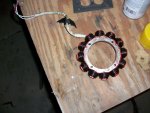
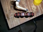
Heres my old/bad (shorted ) stator
Darn thing looked brand new, the ( used) stator I bought to replace it with looked so bad in comparison that when I went to reassemble I grabbed the old one and started putting it back on :doh:
 

Attachments

David Sims

New member
53
0
0
Location
Middle Georgia
It looks like you found the culprit. You may be able to fix that problem...

Obviously you are making voltage with the stator, and the tests in the TM come out good (resistance test and ground test). One time I had a small briggs engine that wouldn't fire. The magnet that passes by the coil was covered with a lot of rust. I sanded it off and she started firing again. The stator on the generator works with the same principal. Magnets embedded inside the inner part of the blower wheel pass by the stator and induce voltage into the coils of the stator.

I would pull the blower wheel off and see if the magnets inside have come loose and maybe fallen out or if they have rusted over, or been painted over (you know how the military loves to CARC EVERYTHING!!!). If they have a layer of paint on them and it is too think, it will not induce the proper voltage. It might be worth a look to see if you can get it running again.
Does the flywheel come off without a puller?
 

Speddmon

Blind squirrel rehabiltator
Super Moderator
Steel Soldiers Supporter
4,640
28
38
Location
Cambridge, Ohio
You actually want to pull the blower wheel off, not the flywheel. You will need a puller of sorts. It is mounted on a tapered shaft with a keyway to keep it from spinning. Take the one center bolt out of the blower wheel and theoretically it should come off just by tapping (gently tapping, the wheel is cast aluminum I believe, the fins break pretty easily) the edge of it with a hammer. If you use a regular puller, I would be worried of breaking the wheel if it is really stuck on there.

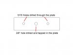
What I did follows. If you look closely at the center of the blower wheel, you'll see the center bolt holding it on, and not far from that bolt you will see a couple of small holes drilled and tapped in the wheel that are I believe 5/16-18. Measure the center to center distance of two of those holes. Then I took a pretty stout piece of 1" bar stock, about 1/2" thick and drilled 3 holes in it. The two outter holes I drilled just a bit over 5/16" so regular 5/16 bolts could pass through them smoothly. The 3rd hole was drilled dead center of the first two 5/16 holes, and tapped for 3/8-16 threads. Bolt the plate to the blower wheel using two 5/16 bolts a few inches long so you can hold the plate away from the wheel an inch or two. The use the center hole with a 3/8" bolt to push against the center of the tapered shaft holding the blower on. You may need to find an old small socket that fits inside the bore of the blower to push against. As you turn the 3/8" bolt in it pulls on the 2 5/16" bolts and puts pressure on the blower wheel. After I had a pretty fair amount of pressure on the wheel (mine was stuck hard enough I had to apply enough pressure on the plate to bend it some), I just tapped the edge with a hammer and it fell off in my hands.

I've attached a drawing of what I'm talking about with my puller plate. It's not to scale or anything like that, just to give you an idea of what I'm talking about.
 

Attachments

David Sims

New member
53
0
0
Location
Middle Georgia
You actually want to pull the blower wheel off, not the flywheel. You will need a puller of sorts. It is mounted on a tapered shaft with a keyway to keep it from spinning. Take the one center bolt out of the blower wheel and theoretically it should come off just by tapping (gently tapping, the wheel is cast aluminum I believe, the fins break pretty easily) the edge of it with a hammer. If you use a regular puller, I would be worried of breaking the wheel if it is really stuck on there.

What I did follows. If you look closely at the center of the blower wheel, you'll see the center bolt holding it on, and not far from that bolt you will see a couple of small holes drilled and tapped in the wheel that are I believe 5/16-18. Measure the center to center distance of two of those holes. Then I took a pretty stout piece of 1" bar stock, about 1/2" thick and drilled 3 holes in it. The two outter holes I drilled just a bit over 5/16" so regular 5/16 bolts could pass through them smoothly. The 3rd hole was drilled dead center of the first two 5/16 holes, and tapped for 3/8-16 threads. Bolt the plate to the blower wheel using two 5/16 bolts a few inches long so you can hold the plate away from the wheel an inch or two. The use the center hole with a 3/8" bolt to push against the center of the tapered shaft holding the blower on. You may need to find an old small socket that fits inside the bore of the blower to push against. As you turn the 3/8" bolt in it pulls on the 2 5/16" bolts and puts pressure on the blower wheel. After I had a pretty fair amount of pressure on the wheel (mine was stuck hard enough I had to apply enough pressure on the plate to bend it some), I just tapped the edge with a hammer and it fell off in my hands.

I've attached a drawing of what I'm talking about with my puller plate. It's not to scale or anything like that, just to give you an idea of what I'm talking about.
I'll give it a try - and I sure appreciate your help!
 

Bill W

Well-known member
1,985
45
48
Location
Brooks,Ga
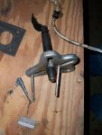
Back out the center bolt that holds the blower to the shaft a few turns so that it not touching the blower then position the tapered puller shaft on the little counter drilled hole on the bolt ( its there for that purpose ) tighten up on the puller jacking bolt and then (as Spedmon said) tap the side of the blower wheel with a hammer and it should break free of the crank shaft. I used a universal puller which is availible at any auto store ( heck I think even Walmart carries it ).
 

Attachments

Last edited:

Speddmon

Blind squirrel rehabiltator
Super Moderator
Steel Soldiers Supporter
4,640
28
38
Location
Cambridge, Ohio
Bill is correct, I forgot about the recess in the center bolt. You can just back it off about 1/4" or so, just so it's free from the wheel, and push against that.

Also, a correctiogn to my earlier post...the threaded holes around the center of the hub are 5/16"-24. They are fine threads not the 5/16"-18 I was thinking.
 

David Sims

New member
53
0
0
Location
Middle Georgia
Speddmon wrote


No I think you had it right the first time the, or at least the threaded holes on my blower are 5/16th course thread
Mine were course thread. I made a puller like Speddmon's but without the center threaded hole. I backed off the center bolt that holds the blower a little less than 1/4" and left the 5/8 socket on the bolt head. Installing the puller I ran the two 5/16th bolts almost all the way into the blower wheel and used washers to get the spacing just right. This was done to help prevent the threads from pulling out of the blower wheel - which was a real concern. For that reason I'm not recommending my method. It worked for me, I tightened on both sides evenly and the blower wheel loosened with a POP.

I sanded the painted inner ring on the blower wheel with fine grit sand paper. Lightly touched the stator ends on the wire wheel on the grinder. Inspected the wires good and found a rubbed place showing exposed wire about 4" from the stator. I was suprised to see bare wire and hoped that it was the culprit. But after repairing the wire and putting it back together the readings were the same.

This has been a good learning experience for me. The charging system is no longer a mystery. (I'm keeping those AC and DC readings straight now) Pulling the blower wheel was not a big deal and the stator came off easily.
I think I'll just go back on with another stator. I sure appreciate the great contributions in this thread. I'm bown away by the sincere interest in my project and energy that you all have put into helping me.

Many thanks and happy generating, David
 
Top
AdBlock Detected

We get it, advertisements are annoying!

Sure, ad-blocking software does a great job at blocking ads, but it also blocks useful features of our website like our supporting vendors. Their ads help keep Steel Soldiers going. Please consider disabling your ad blockers for the site. Thanks!

I've Disabled AdBlock
No Thanks