• Steel Soldiers now has a few new forums, read more about it at: New Munitions Forums!

  • Microsoft MSN, Live, Hotmail, Outlook email users may not be receiving emails. We are working to resolve this issue. Please add support@steelsoldiers.com to your trusted contacts.

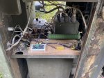
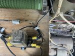
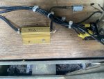
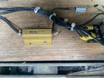
Mep004 circuit to replace faulty voltage regulator. This was designed by member peapvp for use until he could rebuild and update the operating l.

catienla

Member
52
43
18
Location
anawalt,wv
Mep004 circuit to replace faulty voltage regulator. This was designed by member peapvp for use until he could rebuild and update the operating l.
 

Attachments

peapvp

Well-known member
Steel Soldiers Supporter
1,103
1,210
113
Location
Basehor, KS
For completeness:

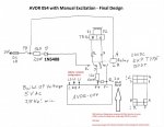
Here is the original Post and the wiring diagram Mike used back in September 2022 while I was rebuilding his A11

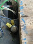
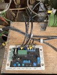
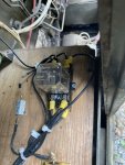
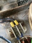
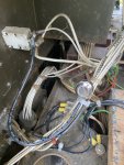
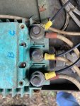
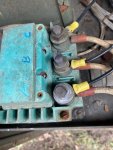
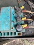
Mike had already a ADVR 054 and built the emergency exciter / voltage regulator setup as you see it in his pictures

According to the message he sent me earlier today, he is in the process of installing his rebuild A11 today which we shipped to him last year in October

Mike asked me if it was ok to post the pictures of the ADVR 054 exciter / voltage - I said OK!

sometimes pretty is not the objective, but does the damn thing work!

According to Mike, it did 👍🏻


original post

wiring diagram

IMG_8448.jpeg
 

catienla

Member
52
43
18
Location
anawalt,wv
I have lived by the old saying "chrome don't get you home" and I agree with Peter it isn't pretty, but it does work flawlessly. I used this setup for approx. 12-15 hours for back-up. Storms and living in the woods doesn't always keep the lights on. I tried to go back and see the cost of parts, ADVR-54 was $140.00, resistors $80.00, in the end it was about $300.00 for everything. Thanks to everyone who assisted in this project, get enough heads on the same page and anything can be done. I'll post how the updated regulator works.
 

2Pbfeet

Well-known member
414
735
93
Location
Mt. Hamilton, CA
This is LOOKING a lot Above my PAY Grade !!! What is all the EXTRA THINGS ??????
I'm sure that @peapvp can explain it better, but if you head over to the data sheet and the owner's manual for the ADVR-54, there are limits on the current and power for the field circuit (F+ & F-). The relay and the other pieces are to flash the coil to help start the generation process. @catienla's nice photos of his neat layout on the board is the transformation of the sketch to reality. If you take your time to compare the sketch pieces to the photos, you can (hopefully) see your way around the sketch, though it helps to know what a power resistor 12Ohm, 500W resistor looks like, and what the parts on a schematic are.

The manual has a few circuits in the back that might help.
IMG_1197.jpeg
 
Last edited:

peapvp

Well-known member
Steel Soldiers Supporter
1,103
1,210
113
Location
Basehor, KS
The answer to this is quite simple:

The exciter coil Resistance (DC) is between 1.5 Ohm to 4 Ohm on the 004; 005; 006; 007; 009 Models

The MINIMUM coil Resistance these aftermarket AVR's can handle is 15 Ohm

WITHOUT the additional parts
as shown in my suggested wiring diagram, this will most likely destroy the AVR and then in turn damage your exciter coil

Proceed at your own risk. We do not assume any liability.
 

Jimmie Morgan

Member
62
12
8
Location
Goodman, Missouri USA
The answer to this is quite simple:

The exciter coil Resistance (DC) is between 1.5 Ohm to 4 Ohm on the 004; 005; 006; 007; 009 Models

The MINIMUM coil Resistance these aftermarket AVR's can handle is 15 Ohm

WITHOUT the additional parts
as shown in my suggested wiring diagram, this will most likely destroy the AVR and then in turn damage your exciter coil

Proceed at your own risk. We do not assume any liability.
Sounds WAY over my pay GRADE . I thought a guy could install the ADVR & GO !!!!!
 
Top