• Steel Soldiers now has a few new forums, read more about it at: New Munitions Forums!

  • Microsoft MSN, Live, Hotmail, Outlook email users may not be receiving emails. We are working to resolve this issue. Please add support@steelsoldiers.com to your trusted contacts.

mep004 reads 0 phase to phase 480 phase to ground

catienla

Member
52
43
18
Location
anawalt,wv
Replaced regulator static exciter with aftermarket advr 54 and added exciter circuit.
Get 0 volts phase to phase 480 phase to ground. Any ideas?
 

peapvp

Well-known member
Steel Soldiers Supporter
1,118
1,244
113
Location
Basehor, KS
Added circuit from dc breaker to F1 with diode and resistor
Ok, because the Datasheet for the AVDR-054 stated:

“Self Excited Analog/Digital 5Amp AVR For use in shunt and generators with auxiliary windings”

at least in the Datasheet I found online through google and there is no further explanation in the Datasheet / Manual on how this “self excited” feature works.
None of their wiring diagrams show any external excitation circuit as you have described.

so I am not sure on what to make out off this.
The only way I can see a “self excitation “ happening is with the residual magnetism in exciter coil assembly when rotor starts rotating

unless I am missing something here

and is your ground lug connected to L0 through a bond (continuity test)?
 

peapvp

Well-known member
Steel Soldiers Supporter
1,118
1,244
113
Location
Basehor, KS
Catienla,

I would like to add some food for thought here.
My guess would be that you have owned this 004 for a while and the original A11 Exciter / AC Voltage Regulator went to AVR heaven.
Just for clarification, did you convert this 004A from 3 Phase to Single Phase by changing the configuration on the reconnection board? This would help me to better understand your setup.

Now, the exciter coil in the 004 is around 3 Ohm DC Resistance. The A11 will put out app. 48 VDC on F1 & F2 when 208VAC are applied to ACVR part of A11.

With this being said, the ADVR-054 manual states:

Excitation Output (F+ to F-)
220V Single phase Continuous 63Vdc 5A = 315 VA
Intermittent 90Vdc 7A 10Sec
Resistance Min.15Ω , Max.100Ω

In comparison the A11 Excitation Output (F1 to F2) :
208V three phase Continuous 48Vdc continues current ?
Intermittent 108Vdc intermittent current?

When we do the math for R = 3 Ohm (Exciter Coil) then the continues current would be I = U/R = 48V / 3 Ohm = 16 Amps DC
and the Power dissipated in the exciter coil would be P = U x I = 768 VA

As we can see, that would be more then double the VA output capability of the ADVR-054

But, the transformer T2 in A11 has a power rating of only app 500VA (de-rated for MIL-SPEC to 300VA)

This tells us two things:
A11 does not put out a DC current to F1 / F2
But it is pulsed sinusoidal current

The A11 is and was an absolute master piece of Analog Power Engineering in the mid sixties when it was designed.

At 48 V and 300 VA we will get a maximum current of I = P / U = 300VA / 48V = 6.25 Arms

since this is pulsed, the actual current is around 2.0 A . We tested this a few years ago in this forum here by adding a 3AG fuse on H1 Leg of Transformer T2
any fuse below 2.5A will blow - 3A works

So the exciter is operated by A11 by a pulsed current, limited to about 2A to 2.25A (app 1/3 of 6.25A) with a variable amplitude between 48V to 108V

The excitation is initiated by the S9-1 switch normally open contact and activates K? (forgot which K)
which will provide 24VDC momentarily to start excitation, then the AVR of A11 takes over and regulates the required pulsed (through SCR's and T2) current for the continued excitation utilizing the AC from the generator.

So, I am not sure on how well the ADVR-054 can actually do the excitation because of the low DC Resistance of the Exciter Coil of 3 Ohm

The advantage of the A11 design, which is quite complex, is the capability of controlling the Generator Output Voltage extremely fast and very precise, even if a large load like a Compressor kicks in.

The Governor (Frequency) is a different story.

The Pulsed system vs a continues DC Current system, prevents the saturation of the Exciter Rotor during commutation and the voltage regulation becomes much faster and by far more precise.

Again, this is just food for thought. I am sure you spent quite some time and thought researching an aftermarket AVR and may want to share this with us.

Peter
 
Last edited:

peapvp

Well-known member
Steel Soldiers Supporter
1,118
1,244
113
Location
Basehor, KS
Found one more info on initial field flashing for a VR350 which is quite similar to the AVDR-054

there is nothing like Chinese manuals translated into English, god forbid we would counterfit a domestically chinese engineered product…….

FE1A5845-FEF4-4ADD-82EA-6FE75E1CE4AA.png
 
Last edited:

peapvp

Well-known member
Steel Soldiers Supporter
1,118
1,244
113
Location
Basehor, KS
Looking through my stuff here when we did Kris’s A11 repair here on SS back in 2019 and he had sent me a NOS VR board for the A11 which had the clock and pulse output plotted after assembly

This shows the two pulses for the two SRC’s which shows the timing of the Phase Angle Control

btw. Capacitor C2 is utilized as a PFC Power Factor Correction in this system, so this cap has to be in perfect condition.


C83147D3-AE00-4C0A-8353-BB7A26E4A0DF.jpeg

35F51383-6E7C-4092-8ECB-F92F9D521259.jpeg
 

catienla

Member
52
43
18
Location
anawalt,wv
Gentlemen, I am working on information given to me by a member jamawieb. He said he had used this set up with the ADVR 54 and the momentary push button, diode and resistor on different generators. Long story short start switch corroded a lug and had to replace. Worked after replacement. Future start no power unless start switch was held up. Was advised regulator was bad, this is where the replacement regulator and exciter circuit came in. No progress since. Generator has not been rewired for single phase been running on L1 and L2 of three phase. Bought in 2010 just started having problems, maybe ran for 60 hours total for power outages. Any help appreciated I am at a wall now. Thanks, Mike
 

peapvp

Well-known member
Steel Soldiers Supporter
1,118
1,244
113
Location
Basehor, KS
Mike,
Just to confirm, you got the diode correctly connected for current flow from DC Breaker=> Pushbutton => Resistor => Anode Diode => Cathode Diode => F+?

also double check that you have F+ and F- connected correctly to your exciter coil

TB1-1 is F1 which is the positive output J13-S on A11
TB1-2 is F2 which is GND J13-R

check the wire numbers in manual to clarify that
you have the coil polarity correct for + and -

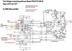
The A11 schematic as reference:


43169784-8C29-4B87-993A-52AE82202A9B.jpeg

some people on smokestack reported that they had AVDR-054 and other aftermarket AVR’s which where dead on arrival or failed a short while after installation due to poor quality.

just to clarify one thing:

this exciter coil will create a output voltage even when you use only a current limiting resistor and a diode with just 24VDC supply
However, this system has no voltage regulation or stabilization

the aftermarket units have a accuracy of +/- 3% to 5% which gives you a 10% range of voltage fluctuations

keep this in mind when powering your house.
A well pump doesn’t care about a 10% fluctuation
 
Last edited:

catienla

Member
52
43
18
Location
anawalt,wv
I think I'm in over my head. Is there a simple way to test gen leads with a voltmeter to make sure gen is still good? As much as I would like to keep what I have, if the gen is bad, would I not be better off to replace it with a more modern gen head? Power was off again for 5 hours this morning, I need to make a decision, winter is just around the corner. I really appreciate and respect you guys being patient and trying to help me. I feel the level of my knowledge about this is so far below everyone who is answering me. Sorry just had to vent. Anyway, I unhooked F1 and F2 and it reads 2.3 ohms across the 2 leads to the exciter coil, is this correct? Working between rainstorms. Thanks, Mike
 

peapvp

Well-known member
Steel Soldiers Supporter
1,118
1,244
113
Location
Basehor, KS
Yes, 2.3 Ohm is fine

can you tell me what your AC voltage is between C and A (with jumper on both B) and then what your DC Voltage is between F+ and F- with exciter coil connected, Genset running after your push button excitation?

this way I can tell you where the problem is


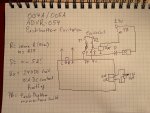
if you can, use this wiring diagram for your push button switch as your current connection does not have a connection from the exciter coil F2 (connected currently on F-) to chassis ground which means there is no 24V going through your coil while pushing your push button hence no excitation is happening in your system

4A73A2A1-BC7C-4D3C-92A0-0A4B02A64EAE.jpeg
 
Last edited:

peapvp

Well-known member
Steel Soldiers Supporter
1,118
1,244
113
Location
Basehor, KS
Mike,

one word of caution, do connect F- from ADVR to chassis ground - this will fry the AVDR
 
Top
AdBlock Detected

We get it, advertisements are annoying!

Sure, ad-blocking software does a great job at blocking ads, but it also blocks useful features of our website like our supporting vendors. Their ads help keep Steel Soldiers going. Please consider disabling your ad blockers for the site. Thanks!

I've Disabled AdBlock
No Thanks