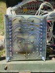
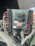
Thank you
@Guyfang !
For the interested reader who may not be intimately familiar of the excitation and voltage regulator scheme in military generators, a short and simple introduction may be in order at this point.
The 0 hundred series employs a Static Exciter and Voltage Regulator
In our case here, it is simply referred to as A11
Static is defined:
lacking in movement, action, or change,
In our case meaning, passive.
In short, the A11 has no active part in the excitation during the start of the generator.
24V is routed into the A11 on one Canon Receptacle through two pins, which connect internally to the two output wires from the AVR circuit and are connected to two pins of another Canon Receptacle, of which the two exciter coil terminals F1 and F2 are connected to.
The active part of the Excitation circuit is a momentary switch (S1 in start position) , a Relay K5, a contact of the speed switch S9, a power resistor and a Diode on PCB A4
These parts will excite the exciter coil.
Once the exciter coil has been excited and the AVR in the A11 starts sensing a AC output voltage above 30VAC, then the A11 takes over and controls the with rheostat selected output voltage of the generator until the generator is shut down.
if you cannot excite the system, then there will be no power output possible. Regardless if A11 is functioning or not.
If you can excite the system, indicated by app 100 VAC on Voltmeter on Panel and your A11 is NOT working, then you will have output power only as long as S1 is held in start position.
If you hold the S1 for too long in the start position (max 15 seconds), then the Diode and/or power resistor on the A5 circuit board will go up in smoke.
This is the number one cause of no excitation.
sometimes, wires between cubicle, A5 box and A11 are broke, frayed, shortened or have corroded contacts in the canon plugs, the S9 switch is broke or K5 is kaput.
In @catienla’s case here, the decision was made to fix A11 first and fix the excitation issue second.


