• Steel Soldiers now has a few new forums, read more about it at: New Munitions Forums!

  • Microsoft MSN, Live, Hotmail, Outlook email users may not be receiving emails. We are working to resolve this issue. Please add support@steelsoldiers.com to your trusted contacts.

MEP803A fuel level adjustment

dav5

Active member
396
183
43
Location
Mono, Ontario
Hi I'm just giving my new MEP803A a workout with break in oil and a variable 70 to 100% load. The fuel tank was totally drained [they popped off the drain wellnut to drain it] and I put in just under 5 gal of fuel. It read full so I knew the sensor was off. It shut down with a low fuel warning after a couple hours. I know I have to reach in and adjust the tank sending unit but how do you adjust it? Is there a set screw to loosen, friction fit? Any advice would be appreciated.
 

DieselAddict

Well-known member
Steel Soldiers Supporter
2,532
2,059
113
Location
Efland, NC
The sending unit assembly adjusts up and down via a fitting on the outside top of the tank. You need to remove the end cover of the generator to get to it. Do you have the manual to reference on the fuel sending unit?
 

dav5

Active member
396
183
43
Location
Mono, Ontario
Thanks again Chris you have bailed me out many times!!! I think I have al the TM's but I can't find anything on fuel sensor adjustment. Is it down by the rad once the top cover is off? Thanks Ted
 

Guyfang

Moderator
Staff member
Moderator
16,766
24,074
113
Location
Burgkunstadt, Germany
Thanks again Chris you have bailed me out many times!!! I think I have al the TM's but I can't find anything on fuel sensor adjustment. Is it down by the rad once the top cover is off? Thanks Ted
Go to page 0078, of the TM-9-6115-642-24. The work package explains how to remove, install, inspect and test the fuel level sending unit. I would do it with an empty tank. Pay attention to item 3, of the installation instructions. A good way to insure that you install it the same way you took it out, is to mark the base of the switch, with a magic marker. Draw your mark on the base and fuel tank. Then you just have to line them up to reinstall it.
 

DieselAddict

Well-known member
Steel Soldiers Supporter
2,532
2,059
113
Location
Efland, NC
Yep. Sounds like you need to troubleshoot the sending unit setup. Guy pointed you in the right direction to get you started.
 

dav5

Active member
396
183
43
Location
Mono, Ontario
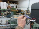
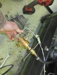
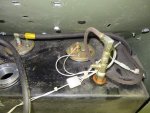
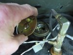
Thanks guys. Here is where I am now. I took the cover off and removed the only thing I could see that had a top adjustment. It had been removed before and all the screws were cross threaded so they had added a whole bunch of black sealant to seal it rather than properly installing the screws. So my first job was to remove it retap the screw holes and reinstall it. It had two floats on it so I assumed it was the sensor for the auxiliary fuel pump.What appeared to be the fuel tank sending unit on the right side had two wires to it and no way to adjust it from the top. I took out the screws and could see a slide mechanism inside with three screws securing it. It is adlusted so it is as short as it can be. I can't get it out to adjust it. I will have to remove the slanted panel that is above it. First I have to clean up my shop it is a mess.
Guyfang I checked the tm with the number you gave me but couldn't find 0078 in it. I know I have seen a TM with similar numbers on here somewhere. Liberated manuals had the same # and it had the removal procedure but not under 0078. My computer skills suck so it is probably my problem.IMG_0706 (1).jpgIMG_0707.jpgIMG_0708.jpgIMG_0709.jpg
 
Last edited:

Guyfang

Moderator
Staff member
Moderator
16,766
24,074
113
Location
Burgkunstadt, Germany
Thanks guys. Here is where I am now. I took the cover off and removed the only thing I could see that had a top adjustment. It had been removed before and all the screws were cross threaded so they had added a whole bunch of black sealant to seal it rather than properly installing the screws. So my first job was to remove it retap the screw holes and reinstall it. It had two floats on it so I assumed it was the sensor for the auxiliary fuel pump.What appeared to be the fuel tank sending unit on the right side had two wires to it and no way to adjust it from the top. I took out the screws and could see a slide mechanism inside with three screws securing it. It is adlusted so it is as short as it can be. I can't get it out to adjust it. I will have to remove the slanted panel that is above it. First I have to clean up my shop it is a mess.
Guyfang I checked the tm with the number you gave me but couldn't find 0078 in it. I know I have seen a TM with similar numbers on here somewhere. Liberated manuals had the same # and it had the removal procedure but not under 0078. My computer skills suck so it is probably my problem.View attachment 669701View attachment 669702View attachment 669703View attachment 669704
OK, let's get started.

First, I am going to see if the TM I uploaded is older than the one I am referring you to. If so, I will upload a newer version.

Second, yes you can get the float out. It's a PITA. But it can be done. If your arms are not as big as Man Mountain Dean, reach in with one arm, and push the float out of the hole, while pulling with the other. And you have to turn the switch one way or the other at the same time.

This appears to be a new style tank. The old ones did not have metal mating surfaces on the top of the tank. It was plastic, with nuts imbedded in the plastic. The upgrade was because of too many leaks and seeps. And it looks like the sending unit is smaller then what I remember. Or your hands are bigger?

You will hate yourself for forty forevers if you try and take the slanted panel off. In the end, you will probably take the entire front end off easier. But, be my guest!

Trust me, the float comes out without jumping through all those hoops. The TM will NOT explain it in detail. Post a picture of the float when you have it out.

Just checked. The problem with the manual is that the new book is dated 2012, BUT its classified C. That means we can not post it in SS. Or give it away. Sorry.
 
Last edited:

dav5

Active member
396
183
43
Location
Mono, Ontario
Thanks Guyfang, I assume you mean reach in through the fill hole. I thought of that but there is a liner that extends down quite a ways. I will try to remove the fill suround and see if the liner comes with it.
 

Guyfang

Moderator
Staff member
Moderator
16,766
24,074
113
Location
Burgkunstadt, Germany
You can, if your arm isn't too big, manage to reach through the filler neck. Or take out the filler neck. But if you do, undo the TOP hose clams on the filler neck. The bottoms ones are sometimes a PITA.
 

Daybreak

2 Star Admiral
Steel Soldiers Supporter
1,522
771
113
Location
Va
Thanks guys. Here is where I am now. I took the cover off and removed the only thing I could see that had a top adjustment. It had been removed before and all the screws were cross threaded so they had added a whole bunch of black sealant to seal it rather than properly installing the screws. So my first job was to remove it retap the screw holes and reinstall it. It had two floats on it so I assumed it was the sensor for the auxiliary fuel pump.What appeared to be the fuel tank sending unit on the right side had two wires to it and no way to adjust it from the top. I took out the screws and could see a slide mechanism inside with three screws securing it. It is adlusted so it is as short as it can be. I can't get it out to adjust it. I will have to remove the slanted panel that is above it. First I have to clean up my shop it is a mess.
Guyfang I checked the tm with the number you gave me but couldn't find 0078 in it. I know I have seen a TM with similar numbers on here somewhere. Liberated manuals had the same # and it had the removal procedure but not under 0078. My computer skills suck so it is probably my problem.
View attachment 669701View attachment 669702View attachment 669703View attachment 669704
Howdy,
OK, let me help out in some layman's terms.
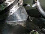
Your first picture. I would clean up as much of the film as possible on the aluminum. The gasket is a standard SAE 5 hole. The rubber around the top is how you position the height of it when it is in the tank. That is where you lower it down until it touches and come back up, er... it says something like 1/16 inch or something. That level sensor is for the auxiliary fuel filling action. The lower float tells it when to turn on the aux pump, and the top is to tell it to turn off the aux pump. That is when you then twist down the locking ring to the rubber ring to hold it at that level.
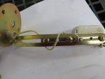
second picture, that's your aux pump.
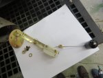
third picture, you can see the fuel return line, you also see the second well nut on the tank. Since you are in this area, check your fuel return line. The replacement is Fuel Return Line info here
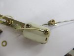
fourth picture, that is the fuel level gauge. standard SAE 5 hole gasket here too.

When Guyfang talks about reaching in... Tank the fuel cap off, pull up on the fill tube and a slight twist in the slots and remove it. Reach into here to inside of the tank. Or find a friend with long skinny arms. :)

Do not button it all up until you have checked everything. It really sucks after you get it all closed and realize the 2 stupid wires are reversed and the gauge does not work. duh
 

dav5

Active member
396
183
43
Location
Mono, Ontario
Thanks Mike. I have the fuel filler tube out but couldn't get past the guides it slides in. I was getting pretty frustrated at that point though. Today is a new day and I will give it another try. My arms are not that large. After Guyfang's advice I won't be removing the slanted panel so I have to get it out. Thanks again.

Ted
 

dav5

Active member
396
183
43
Location
Mono, Ontario
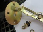
Well sometimes it's best to quit when you are frustrated have a couple beers and go to bed. In my youth I would have ploughed ahead and broken something. I got the sender out this morning. I noticed the slide mechanism was bolted to the round attachment plate. Once I separated them I was able to bend the slide and pry it out. It was still a bitch of a job. There was no way I could get my arm far enough into the filler to reach it from below and the filler flange bolts all had screws with nuts that I couldn't access to get it back on if I removed it. The measurement from the top of the tank to the bottom is 10.25 inches and that was what the sender was set at so I don't know what is going on. My suspician is that they installed it so the float was binding. The ohms reading is right on.IMG_0718.jpgIMG_0715.jpgIMG_0716.jpgIMG_0717.jpg
 

Guyfang

Moderator
Staff member
Moderator
16,766
24,074
113
Location
Burgkunstadt, Germany
One thing to keep in mind is that the military uses lots of things that need this same type float. So sometimes people get a float, unwrap it, and stick it in, without checking to see if the float is adjusted to the same length, as the old one. So they toss it in, and then it will not read, just like the old one. The TM does not tell you what the length is. It's been too long for me to remember what the length is, so unless someone has one out, and can measure, you are going to have to maybe try it once or twice.

Did you mark the float before taking it out? So you know how it was orientated? And that could also have been a problem. If it was turned in the wrong direction, the float assembly could have been hitting the back of the tank, on the slanted side.

In any case, when the tank is empty, the float should almost touch the bottom of the tank. When full, it should almost be at the top. A little room is necessary to allow for expansion. Like Mike said, the gasket is a standard SAE 5 hole. I have NEVER used silicone, or any other sealing compound on a TQG fuel tank. Just the paper gasket. You don't need it if everything is done right. All it does is screw up the gasket, so you cant use it again. The same with every other opening on the tank.

Make sure the float and float rod are tight when you replace the sending unit. I once opened up a tank to find 2 or 3 floats, complete with rods, bobbing around in the tank. One of them got tangled up with the 4th installed sending unit float, causing it not to work and making me think it needed replacing. Just because of all the junk floating around in the tank.

Did you remove the entire filler neck? Look at page 2-114, figure 2-21, Items 21-27, TM 9-6115-642-24. Did you take all that out? Just curious. Because with all that crap out, you should be able to reach inside the tank fairly far.
 

dav5

Active member
396
183
43
Location
Mono, Ontario
No I started to remove the filler neck but then I decided to take the plate off the sending unit and pull it out instead. With the cross threaded screws and all the goo they used I didn't want to assume that they had it oriented right. Also taking it apart probably changed the orientation. I played with it until the fuel gauge seemed to be reading right. The low fuel light was coming on with about 2 inches of fuel in the tank so I'm happy with that and it registered full when I filled the tank. If it is still acting up I will do further troubleshooting. At least I know now that the sending unit is good. The ohms readings were right on. Thanks as usual for all the great info.
Ted
 
Last edited:

dav5

Active member
396
183
43
Location
Mono, Ontario
I was just reading a post by Zarathustra "NO FUEL error on 802a/803a when there is actually fuel in the tank" from 2015. He gives an excellent description of the low fuel sensor. He also states that the holes in the gasket are not evenly spaced. That was my feeling as well. I don't think it is a SAE 5 hole spacing.The screws on both the low fuel sensor and the fuel level sensor were on a tilt and cross threaded when I took them apart. When I retapped the holes and tried to install them the one screw went in fine but the rest would only go in on an angle. I kept rotating the sensor and trying to get the screws in without cross threading. I finally found an orientation where all the screws went in straight with no crossthreading. I think there is only one position where all the screw holes line up.
 
Last edited:
Top