• Steel Soldiers now has a few new forums, read more about it at: New Munitions Forums!

  • Microsoft MSN, Live, Hotmail, Outlook email users may not be receiving emails. We are working to resolve this issue. Please add support@steelsoldiers.com to your trusted contacts.

MEP831A won’t turn off only when disconnecting battery

kloppk

Well-known member
Steel Soldiers Supporter
2,145
3,526
113
Location
Pepperell, Massachusetts
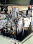
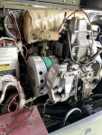
From your two pictures it would appear that someone has messed with the adjustment of the electromechanical governor.
At no load the round "target" on the actuator arm should be 5/16" away from the magnet. Your gap in picture 1 looks way wider than than.
The gap has to be set correctly for the set to properly shut down when S1 is moved to STOP.
The magnet is suppose to "capture" the target and hold it against the magnet. Doing so cuts off the fuel supply to the injector causing the engine to shut down.
In the TM section of this forum you can download the Technical Manuals for your generator. Specifically the TM that ends in -13&P has a section it it on how to adjust the governor system.

If you can post up some close up photo's of the governor area.
 

Leonardo82nd

Active member
Steel Soldiers Supporter
118
70
28
Location
Edinburg Texas
From your two pictures it would appear that someone has messed with the adjustment of the electromechanical governor.
At no load the round "target" on the actuator arm should be 5/16" away from the magnet. Your gap in picture 1 looks way wider than than.
The gap has to be set correctly for the set to properly shut down when S1 is moved to STOP.
The magnet is suppose to "capture" the target and hold it against the magnet. Doing so cuts off the fuel supply to the injector causing the engine to shut down.
In the TM section of this forum you can download the Technical Manuals for your generator. Specifically the TM that ends in -13&P has a section it it on how to adjust the governor system.

If you can post up some close up photo's of the governor area.
 

Floridianson

Well-known member
Steel Soldiers Supporter
7,409
2,503
113
Location
Interlachen Fl.
Kloppk has helped me with my problems as I know nothing about mine.
Maybe I am wrong but your last pictures you have the black throttle knob in the off position. I believe that should be in the run / start position and with motor no load running then you measure the gap?
 

kloppk

Well-known member
Steel Soldiers Supporter
2,145
3,526
113
Location
Pepperell, Massachusetts
Yes, the Black knob should be in the START position and locked in place. It should remain locked in the START position at all times.

Observations from looking at your pictures...
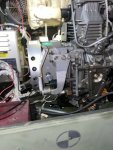
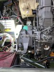
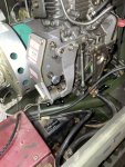
1) The Green Governor spring is in the correct position - Good
2) The top adjustment bolt has had the factory locking wire removed indicating someone messed with the factory adjustment - Bad
3) The lock nut on the actuator rod is not locking the adjustment of the upper section of the rod assembly which will allow the length adjustment to drift - Bad

Is the first picture in your first post of the set running or not running?

Have you downloaded the -13&P TM and found the adjustment procedure?
 

Leonardo82nd

Active member
Steel Soldiers Supporter
118
70
28
Location
Edinburg Texas
Yes, the Black knob should be in the START position and locked in place. It should remain locked in the START position at all times.

Observations from looking at your pictures...
1) The Green Governor spring is in the correct position - Good
2) The top adjustment bolt has had the factory locking wire removed indicating someone messed with the factory adjustment - Bad
3) The lock nut on the actuator rod is not locking the adjustment of the upper section of the rod assembly which will allow the length adjustment to drift - Bad

Is the first picture in your first post of the set running or not running?

Have you downloaded the -13&P TM and found the adjustment procedure?
sorry for the delayed response, was ill. ALL of the photos are of the gen set (off) NOT running.
can you’ll point me in the right direction to fixing issue #2 , perhaps purchasing the factory/ after-market “locking wire“, I have downloaded the 13&P TM-yes . I’m still a bit confused on how to fix it.
 

kloppk

Well-known member
Steel Soldiers Supporter
2,145
3,526
113
Location
Pepperell, Massachusetts
I'll post up a measurement of approximately where the top adjustment screw should be set.

You don't need the locking wire. It along with a lead seal are installed at the factory once the set is adjusted and is there as a reminder not to mess with it. There is also a lower adjusting screw but I couldn't see it in your pics and if it still had the locking wire on it.

If you PM me your email address I'll send you a better version of the whole adjustment process. Better than what's in the -13&P TM.
 

kloppk

Well-known member
Steel Soldiers Supporter
2,145
3,526
113
Location
Pepperell, Massachusetts
Also it wouldn't hurt to purchase Kloppks new controller
Send me that better set up procedure I'd love to check it out
I's the latest version off GAC's website. Has color pictures, where to have the governor springs should be, how to do the adjustments and a step to adjust the Start/Stop knob.

I'll upload it to the TM section and post the link in this thread in a bit. Correction.....

Correction... apparently I not longer have sufficient privileges to upload to the Generator TM section :(
So much for trying to help those with 831's..
 
Last edited:

kloppk

Well-known member
Steel Soldiers Supporter
2,145
3,526
113
Location
Pepperell, Massachusetts
I'll post up a measurement of approximately where the top adjustment screw should be set.
You ought to set it to be 0.775" for starters. That measurement is from the top of the head of the bolt to the plate it screws into.
Be sure to loosen the Black knob before adjusting the top bolt. Once the height is set and the lock nut tightened then move the Black knob as far as possible toward the START position and lock it in place.

Then adjust the set per the procedure I emailed you.
 

Leonardo82nd

Active member
Steel Soldiers Supporter
118
70
28
Location
Edinburg Texas
You ought to set it to be 0.775" for starters. That measurement is from the top of the head of the bolt to the plate it screws into.
Be sure to loosen the Black knob before adjusting the top bolt. Once the height is set and the lock nut tightened then move the Black knob as far as possible toward the START position and lock it in place.

Then adjust the set per the procedure I emailed you.
Thank you , ok we will follow those directions. I will post completed photos and updated status.
 

Guyfang

Moderator
Staff member
Moderator
16,766
24,082
113
Location
Burgkunstadt, Germany
I's the latest version off GAC's website. Has color pictures, where to have the governor springs should be, how to do the adjustments and a step to adjust the Start/Stop knob.

I'll upload it to the TM section and post the link in this thread in a bit. Correction.....

Correction... apparently I not longer have sufficient privileges to upload to the Generator TM section :(
So much for trying to help those with 831's..
Send it to me. I will give a try. Unless something has changed, should be a go, unless its too big.
 

Dewie38

Active member
152
189
43
Location
Milford Ct
GAC's web site adjustment of the start stop knob is incorrect.
Other than that the procedure does include things that I never wrote in the original procedure, when we manufactured some 25 thousand 3 kW's we had new engines that we knew had the spring in the proper hole etc.
 
Top
AdBlock Detected

We get it, advertisements are annoying!

Sure, ad-blocking software does a great job at blocking ads, but it also blocks useful features of our website like our supporting vendors. Their ads help keep Steel Soldiers going. Please consider disabling your ad blockers for the site. Thanks!

I've Disabled AdBlock
No Thanks