• Steel Soldiers now has a few new forums, read more about it at: New Munitions Forums!

  • Microsoft MSN, Live, Hotmail, Outlook email users may not be receiving emails. We are working to resolve this issue. Please add support@steelsoldiers.com to your trusted contacts.

More PCB questions

Special Ed

New member
7
2
3
Location
Wied, TX
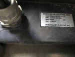
Howdy all. A couple of questions.... but first thanks to those who answered my last post and suggested the grounding harness. I did, it worked like a charm. Now everything is working on the truck except the ammeter and the wait light.
I have the old prestolite white label PCB. In reading the forums, Is the wait light supposed to come on with the white label PCB ? ,There’s no “ wait for the light to extinguish to start” sticker, and everything else is there fresh from the KS guard. Also, in reading the forums, it seems like this PCB is somewhat repairable, containing basically a few 24 V relays... is this true?
I re-grounded my gauge cluster, including the individual gauges.... I’m still showing it not charging when the truck runs. The maintenance history and “people tinkering with it” factor is fairly high, as it did not have batteries when we got it and I would imagine it was started this way several times by jumping at the surplus yard. it does not seem unlikely that it might have been jumped wrong or backwards.
what else can I check. Everything works except the charging and wait light.
Thanks,
Jim
13BCD3BD-092C-4623-B227-D0D1501AE385.jpeg
 
Last edited:

papakb

Well-known member
2,285
1,185
113
Location
San Jose, Ca
First of all there is no ammeter in a HMMWV. That gauge on the instrument cluster is merely a voltmeter. It does not display charge/discharge current.

Yes, the Prestolite boxes are probably the simplest of the control boxes and have a number of 24v relays in them.

In summertime when the weather is hot enough the glow plug controller tells the control box that it isn't necessary to power up the glow plugs so not seeing a "wait to start" light isn't out of line in the summer. Especially in Texas this time of year. It's a great time to test the glow plugs unless your working outside. It's a good practice to get into that any time you connect or disconnect the control box you want to make sure the batteries are disconnected first.
 

Retiredwarhorses

Well-known member
Steel Soldiers Supporter
4,400
4,182
113
Location
Brentwood, Calif
The PCB box you have is junk. As well as the glow plug controller in the water crossover.
buy an EESS with TSU and change all you glow plugs at the same time.
 

Special Ed

New member
7
2
3
Location
Wied, TX
0k, I’ve sort of gathered Thru reading other posts that this PCB isn’t the best. I need the vehicle to be reliable so will change to the EESS and TSU and glow plugs. Is this basically a plug and play replacement, or is more involved. In looking to source there components, I can’t seem to find a vendor.... any suggestions?
One last question. I’m in a hot climate, and am not that concerned with the glow plug or wait to start light. The truck starts and runs well, the voltmeter is really my biggest concern. Anyway, what makes these PCB boxes So undesirable? It seems like if they are comprised of a few relays they would be simpler to troubleshoot/repair/replace than the more recent boxes.
Thanks again
Jim
 

TOBASH

Father, Surgeon, Cantankerous Grouch
Steel Soldiers Supporter
Supporting Vendor
3,582
3,491
113
Location
Brooklyn, NY
The PCB box you have is junk. As well as the glow plug controller in the water crossover.
buy an EESS with TSU and change all you glow plugs at the same time.
A PCB or a new EESS is expensive. I would consider keeping what you have until it fails. RWH is a great guy and his is also a valid point. You could always buy one and keep it in the storage area as an emergency spare.

I decided to pull my SSI PCB and bypass the "electrics" with 2 - 200amp solenoids, a few wires, a new pushbutton, and a shiny new LED to indicate when solenoids are active.

You might not want to go this route however I will post a video of what I did (this coming weekend). Although others have done this (even a movie studio in California), you might not want to as these are 150 amp items that can generate electrical fires, BUT the video will also explain how a PCB/EESS works and how to troubleshoot it. Just take the video with a grain of salt and don't do what I did... Just learn from it.

Best,

T
 
Last edited:

Special Ed

New member
7
2
3
Location
Wied, TX
Thanks everyone. I’m still cogitating on this one, and looking at the various functions of the box. Functional glow plugs are not an issue here in South Texas, but of course everything else is. It might be that just buying a new box and controller , and keep using this one until it fails is the way to go. I still have not found a source for a new one though. Plenty of used stuff on eBay but I’m not particularly fond of pigs in the poke.
I like the idea of replacing the box entirely with relays... but why so big? Outside of the starter being engaged, I can’t think of a circuit that would draw anywhere close to that.
Also, has anyone considered or built a control box using an Arduino or Rasberry programmable microcontroller? They are really cheap ($20) and Controlling multiple circuits with either is right up their alley, regardless of draw. Programming it is easy c code. Just a thought.
 

TOBASH

Father, Surgeon, Cantankerous Grouch
Steel Soldiers Supporter
Supporting Vendor
3,582
3,491
113
Location
Brooklyn, NY
Thanks everyone. ...
I like the idea of replacing the box entirely with relays... but why so big? Outside of the starter being engaged, I can’t think of a circuit that would draw anywhere close to that.
Also, has anyone considered or built a control box using an Arduino or Rasberry programmable microcontroller? They are really cheap ($20) and Controlling multiple circuits with either is right up their alley, regardless of draw. Programming it is easy c code. Just a thought.
The glow plugs pull up to 150 amps so the solenoids need to be able to carry that current.

Why would you want to computerize a device that just needs a pushbutton and a count to three Mississippi?

THERE NEVER SHOULD HAVE BEEN A PCB BOX AND IT NEVER SHOULD HAVE BEEN COMPUTERIZED! Its only purpose is to light up the glow plugs and then switch over to allowing the engine to run. My other Diesel vehicles have no PCB, just pushbuttons.

IMHO, AMG should have just placed a button with a timer so that if the button was held beyond 5 seconds the timer would cut it off to prevent glowplug damage.
 

Special Ed

New member
7
2
3
Location
Wied, TX
The glow plugs pull up to 150 amps so the solenoids need to be able to carry that current.

Why would you want to computerize a device that just needs a pushbutton and a count to three Mississippi?

THERE NEVER SHOULD HAVE BEEN A PCB BOX AND IT NEVER SHOULD HAVE BEEN COMPUTERIZED! Its only purpose is to light up the glow plugs and then switch over to allowing the engine to run. My other Diesel vehicles have no PCB, just pushbuttons.

IMHO, AMG should have just placed a button with a timer so that if the button was held beyond 5 seconds the timer would cut it off to prevent glowplug damage.
I’m not trying to computerize anything, and it’s really not my first choice, but looking at the circuitry in the box, it’s obvious that it’s controlling more than the glow plug timer. If that were the case, a $5 rotary timer switch wired to solenoid would be the simplest fix, and eliminate the fire hazard previously mentioned. In looking at the newer box innards pictured on this forum there are 3 MOSFETs that I’m guessing are there controlling more than glow plugs. The smart start boxes are solid state anyway, so using a microcontroller eliminates much of the antiquated circuitry. If I can determine all the parameters the box controls, it’s really possible I could build a reliable replacement for (guessing) less than $50.
 

Retiredwarhorses

Well-known member
Steel Soldiers Supporter
4,400
4,182
113
Location
Brentwood, Calif
0k, I’ve sort of gathered Thru reading other posts that this PCB isn’t the best. I need the vehicle to be reliable so will change to the EESS and TSU and glow plugs. Is this basically a plug and play replacement, or is more involved. In looking to source there components, I can’t seem to find a vendor.... any suggestions?
One last question. I’m in a hot climate, and am not that concerned with the glow plug or wait to start light. The truck starts and runs well, the voltmeter is really my biggest concern. Anyway, what makes these PCB boxes So undesirable? It seems like if they are comprised of a few relays they would be simpler to troubleshoot/repair/replace than the more recent boxes.
Thanks again
Jim
The GP’s will cycle based on the engine temp, not the ambient outside air temp.
The charging of the battery runs through the PCB/EESS box...So if you don’t show charging, check with a volt meter at the generator and than at the batteries to see what readings you get.
 

TOBASH

Father, Surgeon, Cantankerous Grouch
Steel Soldiers Supporter
Supporting Vendor
3,582
3,491
113
Location
Brooklyn, NY
I’m not trying to computerize anything, and it’s really not my first choice, but looking at the circuitry in the box, it’s obvious that it’s controlling more than the glow plug timer. If that were the case, a $5 rotary timer switch wired to solenoid would be the simplest fix, and eliminate the fire hazard previously mentioned. In looking at the newer box innards pictured on this forum there are 3 MOSFETs that I’m guessing are there controlling more than glow plugs. The smart start boxes are solid state anyway, so using a microcontroller eliminates much of the antiquated circuitry. If I can determine all the parameters the box controls, it’s really possible I could build a reliable replacement for (guessing) less than $50.
Don’t let the Mosfets and IC’s blind you to what this piece of crap really is. I have opened and dissected almost all of the EESS/PCB brands. Ametek, Prestolite, SSI, Nartron. Nartron EESS, KDS Green, KDS, KDS EESS...

It is a glow plug timer, that then switches over to allow current to flow to the rest of the systems after successful glow plug initiation and successful engine rotation as measured via alternator output. It has inputs that won't allow start if tranny is not in neutral or park, and it won't allow start if glow plug temp sensor does not give proper feedback (unless you have a KDS green box).

The PCB is stupid, a waste of money and effort, and is a source of constant grief. The internals utilize cheap electronics in many cases that blow out.

Bypass costs more than $50, but much less than the $1k people are charging for an EESS with matching glow plug sensor.
 
Last edited:

TOBASH

Father, Surgeon, Cantankerous Grouch
Steel Soldiers Supporter
Supporting Vendor
3,582
3,491
113
Location
Brooklyn, NY
Do you have to change the glow plugs when putting a new PCB or EESS box in?
You need to replace the glow plug temperature sensor, but not the glow plugs.

What I mean is that all boxes except KDS Green use a sensor that must be matched to the PCB/EESS. You should buy them as a set to ensure proper match.
 

Nucleo

New member
2
0
1
Location
Westminster/Maryland
Don’t let the Mosfets and IC’s blind you to what this piece of crap really is. I have opened and dissected almost all of the EESS/PCB brands. Ametek, Prestolite, SSI, Nartron. Nartron EESS, KDS Green, KDS, KDS EESS...

It is a glow plug timer, that then switches over to allow current to flow to the rest of the systems after successful glow plug initiation and successful engine rotation as measured via alternator output. It has inputs that won't allow start if tranny is not in neutral or park, and it won't allow start if glow plug temp sensor does not give proper feedback (unless you have a KDS green box).

The PCB is stupid, a waste of money and effort, and is a source of constant grief. The internals utilize cheap electronics in many cases that blow out.

Bypass costs more than $50, but much less than the $1k people are charging for an EESS with matching glow plug sensor.
Hello TOBASH

Thanks for sharing your knowledge and the schematics . I own one of those infamous KDS box that blew a year ago after I attempted to start my HV on a cold day with the original batteries not fully charged. I can still start the engine on a warm day but the pre-heating phase is gone. I took the box apart to see what was going on and I was wondering about the best approach on retrofitting the components. Could you share a pic of your alteration so I can get inspired Thank You . Nuc.
 

TOBASH

Father, Surgeon, Cantankerous Grouch
Steel Soldiers Supporter
Supporting Vendor
3,582
3,491
113
Location
Brooklyn, NY
Hello TOBASH

Thanks for sharing your knowledge and the schematics . I own one of those infamous KDS box that blew a year ago after I attempted to start my HV on a cold day with the original batteries not fully charged. I can still start the engine on a warm day but the pre-heating phase is gone. I took the box apart to see what was going on and I was wondering about the best approach on retrofitting the components. Could you share a pic of your alteration so I can get inspired Thank You . Nuc.
Absolutely,

I have been busy but I will get to it ASAP. Lots of people asking.

Best,

T
 

Nucleo

New member
2
0
1
Location
Westminster/Maryland
Hello TOBASH

Thanks for sharing your knowledge and the schematics . I own one of those infamous KDS box that blew a year ago after I attempted to start my HV on a cold day with the original batteries not fully charged. I can still start the engine on a warm day but the pre-heating phase is gone. I took the box apart to see what was going on and I was wondering about the best approach on retrofitting the components. Could you share a pic of your alteration so I can get inspired Thank You . Nuc.
Absolutely,

I have been busy but I will get to it ASAP. Lots of people asking.

Best,

T
Hello Tobash,

Did you post anything lately related to the fix for the KDS box such as video or pictures ? I

Thx

Nuc
 

Milcommoguy

Well-known member
Supporting Vendor
1,710
2,265
113
Location
Rosamond, CA
Hello Tobash,

Did you post anything lately related to the fix for the KDS box such as video or pictures ? I

Thx

Nuc
Release for general info...........The original "CAMO BOX"

I CAMO, am building the first run of the "CAMO BOX" as mention from time to time here on SS.

This DIY kit meets all the requirements needed for proper, reliable HumV electrical start and glow operation.

Requires NO soldering, NO crimping, cutting, splicing to factory wiring, NO over engineering and NO MORE headaches... in an easy to build, step by step instructions with pictures (we all like pictures) using basic hand tools in an hour or two.

Much work and testing has gone into this by myself, so YOU the owner will have a clear understanding of the goings on. I believe knowledge of the run, start and glow under your control for the HumV system is no different than brakes, half shafts, cooling, fuel pump and all the other greasy stuff you work on to keep YOUR HumV happy.:-D

The kit will clear the "magic" of those expensive box woes. Knowledge is power. The "CAMO BOX" puts YOU back in the driver seat and money back in your wallet.

I will admit... There as been a little set back due to... and this is NO BS... with supply chain / COVID to get to full speed with vendors scrambling to meet my requests. My ears have been pressed against the phone for days or at the drafting table to make it happen.

Get a nice step drill 3/16 to 5/8 and get ready.

PM me with your email address to placed on the list.

"CAMO BOX"..... soon to be under your dash, CAMO
 
Last edited:
Top
AdBlock Detected

We get it, advertisements are annoying!

Sure, ad-blocking software does a great job at blocking ads, but it also blocks useful features of our website like our supporting vendors. Their ads help keep Steel Soldiers going. Please consider disabling your ad blockers for the site. Thanks!

I've Disabled AdBlock
No Thanks