• Steel Soldiers now has a few new forums, read more about it at: New Munitions Forums!

  • Microsoft MSN, Live, Hotmail, Outlook email users may not be receiving emails. We are working to resolve this issue. Please add support@steelsoldiers.com to your trusted contacts.

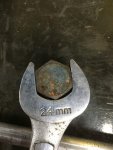
Need 803 parts, crankshaft bolt.

porkysplace

Well-known member
Steel Soldiers Supporter
9,604
1,491
113
Location
mid- michigan
What are the dimensions of this specific bolt? Unless its some weird dimensions/thread I would think it should be available at most any place that carries left hand thread bolts at a fraction of the obscene prices being asked in some places.
Run the NSN/PART NUMBER through www.parttarget.com it should give you the specs. If you get it at a off the shelf bolt house you need to get the correct hardness bolt.
Wrong link


With this search;
https://www.google.com/search?sourc.....0...1c.1.64.psy-ab..1.0.0.0...0.-s92iV252mk
 
Last edited:

Farmitall

Well-known member
Steel Soldiers Supporter
544
276
63
Location
Eubank, KY
Run the NSN/PART NUMBER through www.parttarget.com it should give you the specs. If you get it at a off the shelf bolt house you need to get the correct hardness bolt.

A google search of the information Daybreak post brought this up.
https://www.wbparts.com/rfq/5305-01-422-6463.html


With this search;
https://www.google.com/search?sourc.....0...1c.1.64.psy-ab..1.0.0.0...0.-s92iV252mk
Thanks, I went through all those references and it still didn't say the dimensions. The one at wbparts shows a right handed thread and we know that the bolt is left handed thread. The words "or larger" are not encouraging either.

If anyone with the correct bolt already out of a set could post its dimensions it would be informational GOLD.
 

Evil Dr. Porkchop

Well-known member
Supporting Vendor
1,964
279
83
Location
Colchester, VT
I'll try to remove the bolt from my parts generator today. How do we know it's left hand thread again? I don't want to break it by starting off the wrong way with a stuck engine. I'll look closely to see if it's marked of course.
 

Farmitall

Well-known member
Steel Soldiers Supporter
544
276
63
Location
Eubank, KY
I'll try to remove the bolt from my parts generator today. How do we know it's left hand thread again? I don't want to break it by starting off the wrong way with a stuck engine. I'll look closely to see if it's marked of course.
Stand by,
Before you do that let me find the reference post and get it here. I just read it last night where someone posted they had broken one or a couple.
 

porkysplace

Well-known member
Steel Soldiers Supporter
9,604
1,491
113
Location
mid- michigan
Thanks, I went through all those references and it still didn't say the dimensions. The one at wbparts shows a right handed thread and we know that the bolt is left handed thread. The words "or larger" are not encouraging either.

If anyone with the correct bolt already out of a set could post its dimensions it would be informational GOLD.
Now that I look at it the came back with a different nsn number thats the wrong link.
 

jamawieb

Well-known member
1,437
555
113
Location
Ripley/TN
I'll try to remove the bolt from my parts generator today. How do we know it's left hand thread again? I don't want to break it by starting off the wrong way with a stuck engine. I'll look closely to see if it's marked of course.
You won't know until it doesn't move. Trust me its left hand threads so if your standing in the front of the pulley bolt, turn it clockwise. I think they put on with 220lbs of torque so it's going to be tight.
 

mepgen

New member
14
1
0
Location
Wboro, VA
Jamawieb is correct, it is left hand threads. Took mine off a few months ago to check the timing on my 803a. It is on there tight! I had to use a three foot cheater bar on a half inch breaker bar (could not get the impact gun on it).
 

Evil Dr. Porkchop

Well-known member
Supporting Vendor
1,964
279
83
Location
Colchester, VT
I'd be surprised if mine was at more than 50 foot pounds.
Left hand threads as stated.
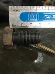
Class 12.9
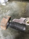
Size looks to be an m16x1.50, about 30 millimeters long not counting the head.
IMG_1945.jpgIMG_1946.jpgIMG_1947.jpg
 

Guyfang

Moderator
Staff member
Moderator
16,662
23,800
113
Location
Burgkunstadt, Germany
You won't know until it doesn't move. Trust me its left hand threads so if your standing in the front of the pulley bolt, turn it clockwise. I think they put on with 220lbs of torque so it's going to be tight.
I once went to a unit that had some Brits working there. They call me, because the bolt had broken off, on not one generator, but two sets! They wanted to know if they should use heat, or maybe pound on the bolt first, before trying to remove it. And what kind of Lock tight was used on the bolt?

After I showed them that it was indeed a left hand bolt, they slunk off like politicians caught with their hands in the till. They had used a one inch drive socket set, and a camouflage pole for an extension. A fat guy stood on the end of it.

Below is a page from the -24 engine TM. Some people learn by READING. Some people learn by watching. Some people just have to piss on the electric fence.

ARMY TM 9-2815-253-24
AIR FORCE TO 38G1-93-2
MARINE CORPS TM 2815-24/3

3-4. DISASSEMBLY AND ASSEMBLY SEQUENCE FOR OVERHAUL.
The following paragraphs provide the sequence of disassembly and assembly for complete overhaul of the engine.
Step-by-step procedures can be found in remaining Sections of Chapter 3.
3-4.1. Disassembly. Every effort must be made to maintain engine in a clean condition and repair oil leaks. With a new
or overhauled engine parts settle during first few hours running and their tightness must be subsequently checked. When
engine is being disassembled all items must be identified, retained in their respective cylinder orientation, and all related
components must be treated similarly. The instructions given deal with individual components and it may be necessary
to remove other components prior to performing certain procedures.
a. Drain engine coolant, fuel, and lubrication systems. Refer to end item maintenance manual.
b. Remove fan drive belt. Refer to end item maintenance manual.
c. Remove battery charging alternator. Refer to end item maintenance manual.
d. Remove fan. Refer to end item maintenance manual.
e. Remove intake and exhaust manifolds. Refer to paragraphs 3-6 and 3-7.
f. Remove fuel pump to injector pipes. Refer to paragraph 3-18.
g. Remove injectors. Refer to paragraph 3-17.
h. Remove cylinder head covers. Refer to paragraph 3-25.
i. Remove valve rockers and pushrods. Refer to paragraph 3-26.
j. Remove water pump. Refer to paragraph 3-10.
k. Remove cylinder head. Refer to paragraph 3-27.
I. Lift out pushrod tubes, rubber seals, and washers. Refer to paragraph 3-27.
m. Remove remaining fuel pipes and fuel filter. Refer to paragraphs 3-15 and 3-16.
n. Remove dipstick and crankcase door. Refer to paragraph 3-20.
o. Remove oil pressure relief valve and the oil strainer. Refer to paragraph 3-21.
p. Remove connecting rod caps. Refer to paragraph 3-30.
q. Carefully remove carbon buildup from the top of cylinder bore.
r. Turn crankshaft until piston is at Top Dead Center (TDC).
s. Lift out pistons and connecting rods. Refer to paragraph 3-30.
t. Insert common screwdriver in flywheel to lock flywheel.
u. Remove crankshaft pulley; left hand thread. Remove screwdriver.
v. Move engine control to stop position.
w. Remove each fuel injection pump. Use care to retain shim pack with each pump. Refer to paragraph 3-13.
x. Remove gear end cover. Refer to paragraph 3-28.
y. Release speeder spring from governor lever assembly.
z. Remove governor lever assembly and governor rack. Refer to paragraph 3-23.
 

doghead

4 Star General /Moderator
Staff member
Super Moderator
Steel Soldiers Supporter
26,246
1,177
113
Location
NY
That would be "anti-clockwise" to them.
 

Farmitall

Well-known member
Steel Soldiers Supporter
544
276
63
Location
Eubank, KY
I once went to a unit that had some Brits working there. They call me, because the bolt had broken off, on not one generator, but two sets! They wanted to know if they should use heat, or maybe pound on the bolt first, before trying to remove it. And what kind of Lock tight was used on the bolt?

After I showed them that it was indeed a left hand bolt, they slunk off like politicians caught with their hands in the till. They had used a one inch drive socket set, and a camouflage pole for an extension. A fat guy stood on the end of it.

Below is a page from the -24 engine TM. Some people learn by READING. Some people learn by watching. Some people just have to piss on the electric fence.

ARMY TM 9-2815-253-24
AIR FORCE TO 38G1-93-2
MARINE CORPS TM 2815-24/3

3-4. DISASSEMBLY AND ASSEMBLY SEQUENCE FOR OVERHAUL.
The following paragraphs provide the sequence of disassembly and assembly for complete overhaul of the engine.
Step-by-step procedures can be found in remaining Sections of Chapter 3.
3-4.1. Disassembly. Every effort must be made to maintain engine in a clean condition and repair oil leaks. With a new
or overhauled engine parts settle during first few hours running and their tightness must be subsequently checked. When
engine is being disassembled all items must be identified, retained in their respective cylinder orientation, and all related
components must be treated similarly. The instructions given deal with individual components and it may be necessary
to remove other components prior to performing certain procedures.
a. Drain engine coolant, fuel, and lubrication systems. Refer to end item maintenance manual.
b. Remove fan drive belt. Refer to end item maintenance manual.
c. Remove battery charging alternator. Refer to end item maintenance manual.
d. Remove fan. Refer to end item maintenance manual.
e. Remove intake and exhaust manifolds. Refer to paragraphs 3-6 and 3-7.
f. Remove fuel pump to injector pipes. Refer to paragraph 3-18.
g. Remove injectors. Refer to paragraph 3-17.
h. Remove cylinder head covers. Refer to paragraph 3-25.
i. Remove valve rockers and pushrods. Refer to paragraph 3-26.
j. Remove water pump. Refer to paragraph 3-10.
k. Remove cylinder head. Refer to paragraph 3-27.
I. Lift out pushrod tubes, rubber seals, and washers. Refer to paragraph 3-27.
m. Remove remaining fuel pipes and fuel filter. Refer to paragraphs 3-15 and 3-16.
n. Remove dipstick and crankcase door. Refer to paragraph 3-20.
o. Remove oil pressure relief valve and the oil strainer. Refer to paragraph 3-21.
p. Remove connecting rod caps. Refer to paragraph 3-30.
q. Carefully remove carbon buildup from the top of cylinder bore.
r. Turn crankshaft until piston is at Top Dead Center (TDC).
s. Lift out pistons and connecting rods. Refer to paragraph 3-30.
t. Insert common screwdriver in flywheel to lock flywheel.
u. Remove crankshaft pulley; left hand thread. Remove screwdriver.
v. Move engine control to stop position.
w. Remove each fuel injection pump. Use care to retain shim pack with each pump. Refer to paragraph 3-13.
x. Remove gear end cover. Refer to paragraph 3-28.
y. Release speeder spring from governor lever assembly.
z. Remove governor lever assembly and governor rack. Refer to paragraph 3-23.
I remember reading that while skimming through that TM. The company should have stamped an L on the bolt head for a man without a book at hand.

Thanks for posting that excerpt.
 

CapePrep

Active member
266
195
43
Location
MA
So, Picked up the 803 this morning. Just as many said the rest of the crank bolt came out by hand. Good sigh! Took the injectors out, sprayed with penetrating oil. Welded a nut on to the remnants of the crank bolt. Leaned on it pretty hard, no movement. Hmmmm, how am I going to try and get this thing turning? Take starter out, put a little strain on flywheel teeth with pry bar. No movement per se. Check oil, it is high on dipstick. Let's drain it. And there it is, water....Not a lot, maybe a cup or 2. Decided to walk away for the night. Let it soak. Have a feeling I will be taking the cylinder head off tomorrow to do an evaluation as to how bad it is. Should I let it sit for a day or more and just try to turn it via the flywheel? Looking forward to hearing opinions. Feel like I should start a new thread for this specific subject, but seem to get scolded when I do that. So, let's let it run and see!
 

csheath

Active member
714
213
43
Location
FL
If you are not in a hurry I would let it soak and keep trying to turn it every so often. I wouldn't lean on it hard but try to work it in both directions if you can.
 

Haoleb

Member
197
7
18
Location
Raymond, Maine
What? No pics?

If it were me I would just start taking off the enclosure panels, exhaust, the head, pull the access panel off the side of the block and start seeing what the problem is. I think either way you found water in there so it would be wise to take it all apart and inspect/clean/repair as required.
 

Guyfang

Moderator
Staff member
Moderator
16,662
23,800
113
Location
Burgkunstadt, Germany
You are not in front of a parking meter. Give it a little time. Reefing it over can cause more damage then not. Give the wonder juice a chance. There is plenty of other things you can be doing in the mean time. Take the skin off. Look at things. Evaluate your problem areas. Are the shock mounts good? Are all your rubber and hoses good? Do you have dirt and trash in every corner? Is the slave recpt. rotated in the right direction? Are there places your wire harness is rubbing? Is the back side of TB1, (the load terminal board) in order? By that I mean are the wires all routed to prevent a short? Are the wires rubbing? I could go on. And in the mean time, your wonder juice is working!!
 

CapePrep

Active member
266
195
43
Location
MA
Appreciating all the suggestions so far guys. Going to let the wonders of chemistry do their thing for a few days and see how it goes. I am in no rush, other than my persistent impatience, so will see how it goes. And yes, I will start taking pics and post accordingly!
 

jamawieb

Well-known member
1,437
555
113
Location
Ripley/TN
Your going to have to let it sit for at least a few days. I usually have to let them sit a couple of days in trans fluid and mystery oil. Then try to move it back and forth slowly. It will take about a week to get it free. These recommendations are also used if you pull the head. Don't even worry with trying to move it with the flywheel because if it not moving by the crank your not going to move it. Really need to pull the head, should take you about 2-3 hours since its your first time. Leave the intake and exhaust manifolds in place when you pull it. It makes the process faster and easier.
 

CapePrep

Active member
266
195
43
Location
MA
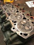
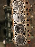
I couldn't wait

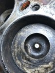
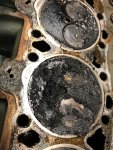
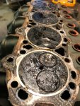
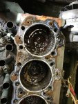
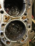
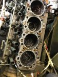
IMG_7883.jpgIMG_7902.jpgSo, after soaking for 24 hours, no movement and my reviewing other threads of locked engines, I decided to pull the head. The following pics speak volumes. IMG_7899.jpgIMG_7897.jpgIMG_7903.jpgIMG_7901.jpgIMG_7900.jpgIMG_7894.jpgIMG_7893.jpgIMG_7892.jpg
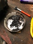
I had been using Kroil and ATF for the soak. I have worked on many gasoline motors and have never seen crud like this on pistons. It was literally a sludge. I included the container where I was putting it so you could see the consistency. It cleaned up pretty easily. What I am more concerned with is the substance on the cylinder walls. It isn't really hard, but it has been there a while. I have scraped most of it off. I am now soaking it in some rust dissolver that is the old real stuff that would probably take chrome off! An old timer gave it to me years ago and told me it would work when nothing else would. I am happy with the fact that there was no real rust in the cylinders. But, contrary to what had been conveyed to the guy I bought it from and obviously to me, that this unit was running recently. I don't think so. So, Let me know what you all think and what I should do next.
 
Last edited:
Top