• Steel Soldiers now has a few new forums, read more about it at: New Munitions Forums!

  • Microsoft MSN, Live, Hotmail, Outlook email users may not be receiving emails. We are working to resolve this issue. Please add support@steelsoldiers.com to your trusted contacts.

Need help MEP-803A

GreaseMonkee63b

New member
14
12
3
Location
Fresno, CA
Hello,

I have an MEP-803A that I am currently working on. A bunch of issues, I am not too familiar with generators and need some assistance.
#1 issue - Generator is not producing AC, no reading on AC gauge, reading 23-25 volts at terminals behind AC gauge, and convenience receptacles. Checked fuse, reset circuit breaker, checked for loose electrical connections and nothing found.

#2 issue - engine keeps running after turning off the main switch and emergency switch as well.

Any assistance would be very helpful at this point.
 

WWRD99

Well-known member
Steel Soldiers Supporter
1,117
1,715
113
Location
York Pa
Hello,

I have an MEP-803A that I am currently working on. A bunch of issues, I am not too familiar with generators and need some assistance.
#1 issue - Generator is not producing AC, no reading on AC gauge, reading 23-25 volts at terminals behind AC gauge, and convenience receptacles. Checked fuse, reset circuit breaker, checked for loose electrical connections and nothing found.

#2 issue - engine keeps running after turning off the main switch and emergency switch as well.

Any assistance would be very helpful at this point.
So I'm kinda new to the 803 life but have been working on mine since June I think...mine started out the same way as it did not make ac power, did not read on the big ac gauge up on the right on the cluster....it did charge the batteries though...so what one smart guy told me to check was when I first start it hold the start lever to start for a few seconds after the engine starts....there should be ac voltage showing then....from what I understand it flashes the field coil and makes power without the regulator....there are 2 fuses in there if a winding mod was done....one is a cap style the is behind the control panel and the other should be wired into the voltage regulator....just note...guys will call that the VR....genset lingo...the engine not shutting down sounds like the fuel solenoid is not shutting off the fuel...the next thing is look in the forum for what's called a TM....they have all the manuals for this on this site online that you can dive in and see if you can figure out what's going on!! If you can I have a pretty involved thread on how I got mine going! Might check it out...good luck!!
Rich
 

GreaseMonkee63b

New member
14
12
3
Location
Fresno, CA
So I'm kinda new to the 803 life but have been working on mine since June I think...mine started out the same way as it did not make ac power, did not read on the big ac gauge up on the right on the cluster....it did charge the batteries though...so what one smart guy told me to check was when I first start it hold the start lever to start for a few seconds after the engine starts....there should be ac voltage showing then....from what I understand it flashes the field coil and makes power without the regulator....there are 2 fuses in there if a winding mod was done....one is a cap style the is behind the control panel and the other should be wired into the voltage regulator....just note...guys will call that the VR....genset lingo...the engine not shutting down sounds like the fuel solenoid is not shutting off the fuel...the next thing is look in the forum for what's called a TM....they have all the manuals for this on this site online that you can dive in and see if you can figure out what's going on!! If you can I have a pretty involved thread on how I got mine going! Might check it out...good luck!!
Rich
Thank you so much, I am familiar with TMs. They are pretty vague and limited on diagnosing. Do you have a picture of the fuses? I have only noticed one fuse that sits below a circuit breaker. That fuse is intact
 

WWRD99

Well-known member
Steel Soldiers Supporter
1,117
1,715
113
Location
York Pa
Thank you so much, I am familiar with TMs. They are pretty vague and limited on diagnosing. Do you have a picture of the fuses? I have only noticed one fuse that sits below a circuit breaker. That fuse is intact
https://www.steelsoldiers.com/threads/mep-803a-getting-it-to-work-my-first-one.197416/#post-2302349 I am not sure if this link will work or if you have to copy and paste it...the first post has pics of my set with fuses showing behind the gauge set. Yes the TM are different from what I am used to as well...but they do have a very good parts blow up.
 

WWRD99

Well-known member
Steel Soldiers Supporter
1,117
1,715
113
Location
York Pa
Thank you so much, I am familiar with TMs. They are pretty vague and limited on diagnosing. Do you have a picture of the fuses? I have only noticed one fuse that sits below a circuit breaker. That fuse is intact
The one fuse is called the FU1 and the other hooked to the VR is a modification that I think is called the quad winding fuse...there's more to that but I would have to search it up....I think it is a sticky in the genset opening page.
 

WWRD99

Well-known member
Steel Soldiers Supporter
1,117
1,715
113
Location
York Pa
The FU1 fuse is the one I checked and it is good.
Ok then the genset should charge the batteries then...does the 24 volt load gauge read high when started then go to 0 volts or so after about 10 minutes? If you don't have the fuse at the vr then you got some diag to play with..like adding the fuse and possibly a new vr...if you go through my thread there is a guy on here who makes them very reasonably priced too that I talk to in my thread.

Sent from my SM-G955U using Tapatalk
 

GreaseMonkee63b

New member
14
12
3
Location
Fresno, CA
Ok then the genset should charge the batteries then...does the 24 volt load gauge read high when started then go to 0 volts or so after about 10 minutes? If you don't have the fuse at the vr then you got some diag to play with..like adding the fuse and possibly a new vr...if you go through my thread there is a guy on here who makes them very reasonably priced too that I talk to in my thread.

Sent from my SM-G955U using Tapatalk
DC voltage reads fine, I can swap out a VR if this is a possibility. I have other sets I can "borrow" parts from.
 

WWRD99

Well-known member
Steel Soldiers Supporter
1,117
1,715
113
Location
York Pa
DC voltage reads fine, I can swap out a VR if this is a possibility. I have other sets I can "borrow" parts from.
Well if you have other 803s then I guess you can swap one...just see if they have the fuse added to it...then swap that too...hate to burn up another one!

Sent from my SM-G955U using Tapatalk
 

nextalcupfan

Well-known member
348
506
93
Location
NW Missouri
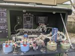
Before I installed the Fuse Mod
Panel 03.jpg
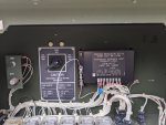
After the Fuse Mod. Also note the small blue varistor between terminals 7 and 8 on the voltage regulator. This is a separate but highly recommended mod that helps protect the VR from voltage spikes.
Quad Fuse and Varistor Mod (11-20-19).jpg

Thank you so much, I am familiar with TMs. They are pretty vague and limited on diagnosing.
Personally I find the Military TM's are very thorough on diagnosing. (Looking through them myself it looks like you did the steps listed in the Operators Manual TM-9-6115-642-10)(TM-9-6115-642-24 is much more detailed for this kind of problem)

21. AC VOLTMETER (VOLTS AC) DOES NOT INDICATE VOLTAGE.
Step 1. Test defective AC Voltmeter (VOLTS AC), paragraph 2-46.2. a. If AC Voltmeter (VOLTS AC) is not defective, do Step 2. b. If defective, replace AC Voltmeter (VOLTS AC), paragraph 2-46.
Step 2. Test for defective AM-VM transfer switch, paragraph 2-52.2. a. If AM-VM transfer switch is not defective, do Step 3. b. If defective, replace AM-VM transfer switch, paragraph 2-52
Step 3. Test for defective VOLTAGE adjust potentiometer, paragraph 2-48.2. a. If VOLTAGE adjust potentiometer is not defective, do Step 4. b. If defective, replace VOLTAGE adjust potentiometer, paragraph 2-48.
Step 4. Test for defective AC voltage regulator, paragraph 2-27.2. a. If AC voltage regulator is not defective, do Step 5. b. If defective, replace AC voltage regulator, paragraph 2-27.
Step 5. Test for defective voltage reconnection switch (S8), paragraph 2-64.3. a. If voltage reconnection switch is not defective, do Step 6. b. If defective, replace voltage reconnection switch, paragraph 2-54.
Step 6. Check AC Voltmeter circuit for breaks or loose connections, refer to Wiring Diagram F&2. If breaks or loose connections are found, repair circuit.

This is from Page 65 in the -24 TM.

You've made a good start but it looks like you've only done Step 1 and Step 6 + some stuff on the DC side.

22. GENERATOR SET FAILS TO GENERATE POWER. Step 1. Test for defective ac circuit interrupter relay (K1), paragraph 2-61.3. a. If AC circuit interrupter is not defective, do Step 2. b. If defective, replace AC circuit interrupter, paragraph 2-61.
Step 2. Test for defective Field Flash relay (K15), paragraph 2-33.2. a. If defective, replace Field Flash relay. b. If Field flash relay is not defective and trouble persists, notify next higher level of maintenance.

I'd like to add step 2 on this one, but as I understand it the relays rarely go bad. Though if it is bad I can link you to an aftermarket one that works as a drop in replacement.

kloppk is the person WWRD99 mentioned earlier, he makes a remote start and monitoring kit, aftermarket (and improved) voltage regulator, and a replacement frequency trip switch (s14)
 

GreaseMonkee63b

New member
14
12
3
Location
Fresno, CA
Before I installed the Fuse Mod
View attachment 822856
After the Fuse Mod. Also note the small blue varistor between terminals 7 and 8 on the voltage regulator. This is a separate but highly recommended mod that helps protect the VR from voltage spikes.
View attachment 822857


Personally I find the Military TM's are very thorough on diagnosing. (Looking through them myself it looks like you did the steps listed in the Operators Manual TM-9-6115-642-10)(TM-9-6115-642-24 is much more detailed for this kind of problem)

21. AC VOLTMETER (VOLTS AC) DOES NOT INDICATE VOLTAGE.
Step 1. Test defective AC Voltmeter (VOLTS AC), paragraph 2-46.2. a. If AC Voltmeter (VOLTS AC) is not defective, do Step 2. b. If defective, replace AC Voltmeter (VOLTS AC), paragraph 2-46.
Step 2. Test for defective AM-VM transfer switch, paragraph 2-52.2. a. If AM-VM transfer switch is not defective, do Step 3. b. If defective, replace AM-VM transfer switch, paragraph 2-52
Step 3. Test for defective VOLTAGE adjust potentiometer, paragraph 2-48.2. a. If VOLTAGE adjust potentiometer is not defective, do Step 4. b. If defective, replace VOLTAGE adjust potentiometer, paragraph 2-48.
Step 4. Test for defective AC voltage regulator, paragraph 2-27.2. a. If AC voltage regulator is not defective, do Step 5. b. If defective, replace AC voltage regulator, paragraph 2-27.
Step 5. Test for defective voltage reconnection switch (S8), paragraph 2-64.3. a. If voltage reconnection switch is not defective, do Step 6. b. If defective, replace voltage reconnection switch, paragraph 2-54.
Step 6. Check AC Voltmeter circuit for breaks or loose connections, refer to Wiring Diagram F&2. If breaks or loose connections are found, repair circuit.

This is from Page 65 in the -24 TM.

You've made a good start but it looks like you've only done Step 1 and Step 6 + some stuff on the DC side.

22. GENERATOR SET FAILS TO GENERATE POWER. Step 1. Test for defective ac circuit interrupter relay (K1), paragraph 2-61.3. a. If AC circuit interrupter is not defective, do Step 2. b. If defective, replace AC circuit interrupter, paragraph 2-61.
Step 2. Test for defective Field Flash relay (K15), paragraph 2-33.2. a. If defective, replace Field Flash relay. b. If Field flash relay is not defective and trouble persists, notify next higher level of maintenance.

I'd like to add step 2 on this one, but as I understand it the relays rarely go bad. Though if it is bad I can link you to an aftermarket one that works as a drop in replacement.

kloppk is the person WWRD99 mentioned earlier, he makes a remote start and monitoring kit, aftermarket (and improved) voltage regulator, and a replacement frequency trip switch (s14)
Awesome info. I will follow through with these steps.
 

nextalcupfan

Well-known member
348
506
93
Location
NW Missouri
Hmm I can't find a section in the TM for "engine fails to shutdown"

The first thing I would check would be is the fuel shutoff solenoid, see if it moves all the way when you switch S1 to off.
If it doesn't unplug the plug and check power, if yes you have something feeding the circuit. (I think someone on here had a bad alternator that did exactly that)
If no check the linkage for binding.

Unfortunately if the solenoid checks out I think you'll have to get into the rack and metering pumps which is beyond my expertise at this time.


I hope we can get you sorted, I just went through a 25 hour power outage with my 803a and was very happy with its performance.
 

nextalcupfan

Well-known member
348
506
93
Location
NW Missouri
After sleeping on it I thought of something simple.
Is the frequency adjusted correctly? If not these sets will not produce proper voltage, and will burn themselves out trying to do so especially if the frequency is too low.

A common error in operating these sets is to "idle" them. That's a one-way ticket to VR destruction.

I'm worried about this because your set won't shut down, possibly indicating rack issues.
 
Top