• Steel Soldiers now has a few new forums, read more about it at: New Munitions Forums!

  • Microsoft MSN, Live, Hotmail, Outlook email users may not be receiving emails. We are working to resolve this issue. Please add support@steelsoldiers.com to your trusted contacts.

need help with starter for my 89 3 kw 24v generator

W8BUH

New member
8
0
0
Location
West Branch , Mi.
I have three MEP 0701a's and in need of some solenoids. I have three of these generators and in need of them to replace them. The one will not start and I'm wondering ENT if the float could be stuck? I seen that there that it looks like there is two floats in the tank. Is it possible that one of them could be stuck so it doesn't start?
ENT I have read some of your post and you have been very helpful..
Thanks
 

jonster

New member
67
0
0
Location
Virginia
There are two floats on the fuel level tube. The bottom one is the low fuel shut off switch, the upper one is the aux fuel pump shut off switch. The bottom one can keep the unit from starting. I have an easy way to test it. Disconnect the wire to the fuel level tube. Unscrew the fuel level tube from the tank. Now, reconnect the wire to the tube and have someone hold it upside down. (so both floats are up) Now turn the master switch to run. The fuel shut off solenoid should click back. When the switch is in the run position, you should hear a click from the relay in the control box when you move the bottom float up and down. You can also jump the solenoid from the battery and test it. Good luck.
 

jonster

New member
67
0
0
Location
Virginia
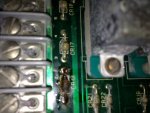
It turns out it was not a diode, but a capacitor, CR14. The capacitor is marked AKK 522. I checked every connection and every wire, could a stuck relay cause that? I flipped all four relays. They are corroded, so I can't read what kind of relays they are. Here is a pic.photo(1).JPG
 

Triple Jim

Well-known member
1,376
292
83
Location
North Carolina
CR14 is a diode. It's a little 1A diode. You can use a 1N4004, 1N4005, 1N4006, or 1N4007 to replace it. What Steelypip said still goes though... it's likely that something overloaded it to make it burn up like that. If you can get me a schematic diagram, I can give you an idea of what to look for that might be likely to have damaged it.

A stuck relay can definitely cause problems like that, so you may be onto something, but I'm just guessing at this point.
 
Last edited:

W8BUH

New member
8
0
0
Location
West Branch , Mi.
Thanks Jonster I will try that one for sure. I thought about trying that too.. Where can you get the solenoids for them? Is there some place that you can cross reference them. The trailer I have has two of those generators on it and there was three solenoids in that tool box so that tells me the go out alot.
 

ETN550

New member
457
9
0
Location
Knoxville, TN
It turns out it was not a diode, but a capacitor, CR14. The capacitor is marked AKK 522. I checked every connection and every wire, could a stuck relay cause that? I flipped all four relays. They are corroded, so I can't read what kind of relays they are. Here is a pic.View attachment 432276
The relays can be flipped. These are $150.00 list, silver soldered, hemetically sealed relays so their external appearance does not mean they are bad inside. I just finished selling a bunch of them from NOS boards used on other units that I bought. The big autcion site might still have a relay board (I think for the 10kw gasoline MEP-018 )that contains 4 of the correct relays for a good price. Just strip off the relays and chuck the board.

Capacitors eventually go bad. Solder in a new equivelent Capacitor and problem solved.

I fill the tank over the bottom float, turn the switch on, listen for the loud fuel control solenoid "clack" and then use a wooden dowell or long tool to push the float down. If it's working the solenoid will clack on and off as the float raises and lowers. All float functions can be bypassed in the control box by using jumper wires on the terminal strips or by disconnection of existing wires on the terminal strips. Just be careful bypassing the top float for the aux pump as the aux pump will not turn off when the tank gets full. There is also a procedure to rewire the top float to make the aux pump start and stop if the existing top aux pump float is bad. The top float has two switches in it and mods can be done if one is bad.

I have not found a good source for the float switch assembly. I would like to either make a new assembly or find a source for new ones. The Chinese electronic suppliers have parts and pieces to make a tube assembly with floats on it. Something i might do some day.
 
Last edited:

Triple Jim

Well-known member
1,376
292
83
Location
North Carolina
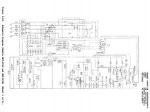
Triple Jim, here is the schematic
I'm afraid I'll need more resolution to be able to read anything on it.

ETN550, I agree that capacitors do fail with age, but as I said above, the burned part is a diode, and they normally do not fail with age during our lifetimes.
 

ETN550

New member
457
9
0
Location
Knoxville, TN
I'm afraid I'll need more resolution to be able to read anything on it.

ETN550, I agree that capacitors do fail with age, but as I said above, the burned part is a diode, and they normally do not fail with age during our lifetimes.
YES agreed. I misread followup post. I believe all the diodes on that board are to block misapplication of reverse current.
 

jonster

New member
67
0
0
Location
Virginia
Okay, I got the thing running, turns out I did have a second bad diode. Thanks Triple Jim! and to everyone else. I am getting no output on the DC charging system, and are the fans on the mep701a supposed to come on right at start up? Miner never came on, and I don't see a temperature switch anywhere on the schematic. The fans seemed to be wired to a very large capacitor, is this a start capacitor or is it radio suppression?
 

Triple Jim

Well-known member
1,376
292
83
Location
North Carolina
I think you're seeing relay contacts that resemble the symbol for a capacitor. When A2S1, the master switch, is in the run position, and A3K4, a pair of contacts of the low fuel shutdown relay, is closed, the "noise kit fan", if you have one, should run. "A3K4", for example, is a set of contacts on the low fuel shutdown relay K4, on board A3.
 

Triple Jim

Well-known member
1,376
292
83
Location
North Carolina
If you have 24V on both sides of CR4 and not at the fan, then the wiring must have a problem. From the schematic, if the battery is installed and charged, the fan should run until the battery runs down, even if the charging system isn't working.
 

ETN550

New member
457
9
0
Location
Knoxville, TN
If you have 24V on both sides of CR4 and not at the fan, then the wiring must have a problem. From the schematic, if the battery is installed and charged, the fan should run until the battery runs down, even if the charging system isn't working.
The fans on the 701A are 120 VAC and run off of the 120 voltage sensing wires that are at the main voltage regulator. If you are making 120vac at the T1-T2 coil and convenience outlet is hot then the fans should run regardless of the 24vdc system. There are some small 3amp fuses in separate holders to the left side of the main voltage regulator. One fuse for each fan. The last 701A I worked on had a bad fan and I had to retrofit a replacement fan. But since neither of your fans work then I suspect bad fans are not the issue. You may remove the white wires from the terminals on the regulator, I forget if the black wires go there too, but in any event the fans can be shorted to household 120vac to see them run. Those big capacitors are required so don't short the fans to 120 at the connector at the fan as that removes the capacitors. The red wire goes to the capacitors. There is one capacitor on the frame on each side below the control box. When I tested the fans I removed the side panel that does not have the door and cut the black and white fan wires and shorted to 120vac on the fan side. After I was done I spliced the wires back. I think you have bad fuses or bad connection somewhere if you have 120vac at the convenience outlet. The only wiring diagram I would trust for this is the one on the control panel lid as it was changed out when the 701A was made from the 016B. JMO.
 

Triple Jim

Well-known member
1,376
292
83
Location
North Carolina
ETN550, thanks for your post. Jonster emailed me a schematic that I thought was correct for his generator, but I just checked, and it's for an MEP-016B, so I've been helping him based on the wrong diagram!
 

jonster

New member
67
0
0
Location
Virginia
My 701a has no schematic inside or outside of the control box, I have been using the closest schematic I can find. I am sure having an actual 701a drawing would help. Thanks again!
 

jonster

New member
67
0
0
Location
Virginia
I went over the entire fan circuit. Finally, I pulled out a spool of red, black and white wire and replaced all of the wires in the circuit. Fans work great! Now on to the DC charging system. I have looked all over the internet for an actual mep701a schematic. I have had no luck. The one TM that comes up is mostly about the trailer that these units sometimes come on. My load meter is also DOA. I have a mep002a, I thought about disconnecting the leads to that load meter, and jumping from the 701a to the mep002a's load meter and seeing if I get a reading. Is there any reason why this may not work? As I said before, I am trying to get this thing 100% by father's day. I was considering mounting a small after-market 10 amp 24 volt charger inside the cabinet, and running it off the convenience outlet circuit. I have read that the charging systems in these units is the weak link. Triple Jim, sorry about the wrong schematic, it is the only one I could find. You advice from the schematic I sent you was dead on. Again, thanks for the help.
 
Top
AdBlock Detected

We get it, advertisements are annoying!

Sure, ad-blocking software does a great job at blocking ads, but it also blocks useful features of our website like our supporting vendors. Their ads help keep Steel Soldiers going. Please consider disabling your ad blockers for the site. Thanks!

I've Disabled AdBlock
No Thanks