• Steel Soldiers now has a few new forums, read more about it at: New Munitions Forums!

  • Microsoft MSN, Live, Hotmail, Outlook email users may not be receiving emails. We are working to resolve this issue. Please add support@steelsoldiers.com to your trusted contacts.

New M1008 Project

Skinny

Well-known member
2,130
488
83
Location
Portsmouth, NH
I have not camped in it yet. I like the enclosed space. I want it to be so that no one is the wiser if the truck is in a parking spot and it doesn't stick out like an RV or travel trailer. I am redoing the insulation and will be putting a diesel hydronic heater to battle the cold.
 

bwilson7990

Member
54
0
6
Location
York, Pennsylvania
A few questions:

Where is the "ground-tree" grounded to?
How far away from the battery is the new power distribution block fused? (looks like the other side of the engine bay - too far IMHO, should be within 18" of the battery, the point is to protect that entire wire from the battery to the distribution block)
The ground tree is bolted to the shelf that the starter relay, volt relay, and Gen 2 relay are fixed to, directly below the heater controls. That shelf is bolted to the underside of the dash same as is oem. The ground tree grounds connections which run through the switches to ground a 3A circuit for glow lights under the dash, 2 relays in the engine bay, a 5A cig lighter/USB combo module, and one 168 light bulb (indicating when manual glow plug circuit is on). One relay is for the 18A lightbar, and the other will be for the custom courtesy light on door switches which is <5A . For both of the relays I am jumping the hot pin to the switch pin as well so it's always switched and the physical switch on the panel connects the ground (to the tree). I felt that there's realistically not much amperage to be grounded on the tree since we're only grounding 3A lights, a 5A cig lighter, and the two relays. Plus the power for the accessories traverses the relay when it's closed, the relay ground itself doesn't carry that load, just enough to close the relay. Thoughts?

As far as the distribution block goes, this is something that I didn't really consider.... All of the accessories that are connected to this distribution block are individually fused based on the amperage of the accessory. My thought was that if any accessory's hot was to ground out it would blow the accessory fuse which is further down the line and would result in breaking the connection to the main hot connection run from the battery. In addition, there are two distribution blocks- the first splits the main run from the battery to the fused distribution box (where accessories are attached) and also to the glow plug hot which has it's own fuse. Because of this, I didn't think it would be necessary to fuse the main power running from the battery. It's only a foot or so further past the engine harness block though to answer your question. Maybe I could get away with adding a fuseable link to the end of the main run from the battery?

I will consult in a few of my other electrical knowledge sources as well, see what they think about this setup, and let you know what I find.

Thanks for your concern and input, much appreciated!
 

bwilson7990

Member
54
0
6
Location
York, Pennsylvania
I have not camped in it yet. I like the enclosed space. I want it to be so that no one is the wiser if the truck is in a parking spot and it doesn't stick out like an RV or travel trailer. I am redoing the insulation and will be putting a diesel hydronic heater to battle the cold.
That sounds badass. Best of luck on all the work.
 

bwilson7990

Member
54
0
6
Location
York, Pennsylvania
A few questions:

Where is the "ground-tree" grounded to?
How far away from the battery is the new power distribution block fused? (looks like the other side of the engine bay - too far IMHO, should be within 18" of the battery, the point is to protect that entire wire from the battery to the distribution block)
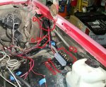
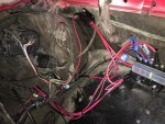
See the attached picture. I drew over it some to highlight the components. D1 is the first split and D2 is where the hots will be connected; GP is the glow plug fuse. The rest of the individual fuses and accessories have not been added in this picture, the connections are run into the engine bay but not terminated. Under the white/frosted cover is where the individual fuses will go for accessories.
 

Attachments

tim292stro

Well-known member
2,118
41
48
Location
S.F. Bay Area/California
Take a moment to read this page - the main website and all of its sub-pages are probably one of the better car electronics pages on the internet IMHO.

There are some basic rules one should follow when dealing with Automotive DC power:
  • Size the circuit wiring by the length and load. Wire should be able to take 125% of the continuous load over its length - make sure you account for ground return in your evaluation of the circuit!!
  • Fuse EVERY circuit to protect the wire from a load or wire fault. The fuse should be as close as practical but no further than 18" from the power-tap or split. The fuse/fusible link is supposed to be the safe weak link rather than turning your wire into a red-hot heater that burns down your ride...
  • Any time a load is added to a system, the full system needs to be evaluated for new weak points and protected against them. This may mean installing a new separate electrical harness if the original harness is unable to support the old loads+new loads.

So, I'm happy to see that you appear to be pulling power from the battery for your new distribution system. What I still don't see is a fuse for the main tap to the battery - that's my biggest concern for your safety :beer:. Here's why I worry, and I'm hoping you continue your interest in this:

In a series circuit (one load after another in a series), the load with the lowest current passage dictates the amount of current the whole circuit can pass. For example a battery, light bulb, and its wire (from the battery to the bulb, and from the bulb back to the battery) - makes a series circuit of battery-wire-bulb-wire-battery. The light bulb has the highest resistance to the passage of current (limits the amount of current) for the whole circuit. In this way, a 900Ah battery will not dump all 900Ah into the bulb, the bulb will merely sip what current it needs out of that pool to do the work its was designed to (more accurately it will only allow the amount of current to pass that its resistance will allow - it limits current flow by design). However, should a wire in that series circuit short the circuit (making the circuit battery-to-wire-to-battery), only the resistance of the wire is what's limiting the amount of current flowing from the battery - wire is designed to have a low resistance so that the work can be done by the devices without losing a lot of power on the way, so the lower the resistance, the higher the flow of current.

On a battery like an Odyssey AGM, the short circuit current can be as high as 5000Amps. A length of 2 gauge copper wire would have somewhere around 0.00015749Ohms/foot - assuming one ran a wire from the battery to the other side of the engine compartment, that might be a length of say 5-feet. The total resistance would be 5 * 0.00015749 Ohms, or 0.00078745 Ohms. If your battery was fully charged at rest we might see 12.8V. Should that wire short to ground without a fuse, we'd be looking at approximately 12.8V / 0.00078745Ω = 16,255 Amps maximum (approximate) the wire would try to carry (on its way to instant vaporization) - which means the only thing limiting the current travelling over that wire would be the ESR (Equivalent Series Resistance) of the battery (5000Amps). Just so you know, 12.8V * 5000A = is 64,000Watts, or 64kW - your entire house probably runs on less than 30kW... That's a very hot wire, like 42 room heaters worth of heating element crammed into a 5-foot wire. :burn:


I think others who coach on electrical stuff here on the forum will agree that you will want to start back at the load, and then work back to the battery to figure out what size wire and fusing you need - but you should always end up with a fuse at the battery to protect the main feed - that one is potentially the most dangerous.

You can expect your glow plus to draw 1600 Watts or more, and whatever else you put on the distribution block(s) you will want to account for. If you don't run all of the loads simultaneously, you can do a smaller circuit size, but then I would add interlocking to ensure that you can't run load combinations that would exceed the ratings of your circuits (like installing a relay that allows you to run a snow plow pump once the engine is warm only, thereby guaranteeing the glow plugs will have stopped running by then).
 

bwilson7990

Member
54
0
6
Location
York, Pennsylvania
tim292stro-

Wow. This is incredible. Mind blown, seriously. If you knew the kind of detailed person I am you'd know how fantastic that was for me to learn. I deeply respect the time you took to write this down and that has certainly adjusted my perspective of how to handle electrical power and accessories. I learned about ohms when I installed my amp and sub woofer in my other car so its incredible to know that the resistance of the large guage wire is that low. I actually have purchased a fuse for that circuit and plan to install it on the battery side of the engine bay. This will ground the entire circuit that will power all of my accessories. They all will be individually fused as well either via the second fused distribution box or immediately after the primary block splitter. Also, I have my glow plugs on a manual momentary push button switch so when using the plow I can be sure that they wont be running at the same time. Again, thank you so much for this. Off to get a start on this now.
 

Skinny

Well-known member
2,130
488
83
Location
Portsmouth, NH
I agree to that theory but the wire heats up and resistance drastically goes up plus the battery would not put that current out once the voltage starts to drop. I'm sure the calculations are a good starting point but that statement is very confusing for someone struggling with basic electricity.
 

tim292stro

Well-known member
2,118
41
48
Location
S.F. Bay Area/California
The "model" I presented is simplified, as dynamic systems are significantly more difficult to explain without first understanding the simpler model.

For your peace of mind, the battery's ESR, chemical reaction rate (due to battery design and chemistry), and temperatures all come into play. Based on the temperatures, the chemical reaction will occur at a specific peak rate. Based on the design there will be a certain rate of electron exchange to the plates and bus bars which has an impedance (an AC power component). The take-away is that once the AC-mode spike subsides, the battery will settle into a power delivery rate that more accurately relates to a DC signal (in truth AC of less than 1Hz). Sure it won't be the full 12.8V - but it'll still be 5000Amps across the wire's resistance (that's the rate that Odyssey determined it can deliver based on its design in a continuous short circuit condition). The wire's resistance at 25C is not what it is at >1000C, that's determined by the temperature resistance coefficient, which for pure copper is roughly +40x10[SUP]-4[/SUP], which means that as the temperature rises the resistance will too (even if it's a tiny multiplier of R[SUB]material[/SUB]*(1.004/degree-Celsius). At the melting point of copper (about 1085C), the resistance/foot of a 2Ga cable would jump from 0.00015749Ohms/foot up to 0.1676071576Ohms/foot - at which point it would still be conducting ~16Amps by itself so it would continue to self-heat until it dripped out of solid and makes an open circuit (just like that fuse I'm advocating he put in [thumbzup]). As the temperature of the copper in the wire rises the resistance of the wire will cause less heat to flow through it, but it's going to be REALLY hot before it has any meaningful effect on the current.

Combustion temperature of most materials under the hood is below 600F/315C - well below the 1085C melting point of copper, and the rating of the jacket (at most under the hood it'll be rated for 250C). In fact as the wire gets hotter than 250C the jacket will melt or burn (you don't have any oil or fuel deposits under your hood right?), the wire will be able to opportunistically short against anything else under the hood it comes into contact with as it gets softer and droops. It would suck to have a flaming hot electrically charged wire drooping onto an injector HP or return line, or the fuel filter hoses, or even the wiper fluid lines (wiper fluid, like antifreeze, is a flammable substance at the right temperatures). Then your first-order ignition source turns into a fueled fire. Pray that doesn't happen while driving so that fresh combustion air is force-fed into the engine bay.

We all carry fire extinguishers onboard right? :beer:
 

bwilson7990

Member
54
0
6
Location
York, Pennsylvania
I agree to that theory but the wire heats up and resistance drastically goes up plus the battery would not put that current out once the voltage starts to drop. I'm sure the calculations are a good starting point but that statement is very confusing for someone struggling with basic electricity.
By no means am I struggling with this, I completely understand everything being discussed here. It's just good experience to talk things out and make sure we're all on the same page so that we can have an effective, educational, and progressive conversation. I know that's not what you were trying to say, but still.
 

Skinny

Well-known member
2,130
488
83
Location
Portsmouth, NH
I apologize if that sounded like it was directed at you. It was more of a broad statement for someone that finds this thread and is trying to follow along.
 

bwilson7990

Member
54
0
6
Location
York, Pennsylvania
Added some fuses and completed the rest of the wiring

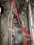
So last night we got to work again and added an inline fuse for the main power run immediately after the connection to the battery (main_fuse pic). We used a 40A fuse for this- everything connected to this distribution running at full capacity shouldn't exceed this (pic has an 80A that came with fuse kit but we swapped for 40A instead). Everything that we have installed so far has been terminated and fused, tested and working. See distribution_connected pic.

Question: What size of fuse (in amps) would be appropriate for the manual glow plug setup on a momentary switch?

We currently are using a 30A fuse as the fuse left by the previous owner was a 40A Motorolla Buss KBJ-G40 glass fuse (which was blown) and I felt like that was too heavy. Glow plugs are working fine on the 30A but I'd like to put in the lowest amperage fuse that I can to adequately protect the glow plug circuit. I've seen that some guys are using 20A momentary switches without issues but I was thinking possibly even lower than that. What do we think?
 

Attachments

bwilson7990

Member
54
0
6
Location
York, Pennsylvania
I apologize if that sounded like it was directed at you. It was more of a broad statement for someone that finds this thread and is trying to follow along.
Oh no you're fine and I appreciate your contributions to this. I just wanted to clarify for anyone else reading so they know they don't need to "dumb it down" for me.
 

bwilson7990

Member
54
0
6
Location
York, Pennsylvania
Wiring wins

Made a few significant breakthroughs last night with this project. When we started working on the truck the Voltmeter was IN/OP, the GEN 1 light was steady on, and the GEN2 light was IN/OP completely; this ended up leaving my buddy stuck about 40 mins away from home at his girlfriends house because of the lack of charging (and knowledge about the truck) which drained the system and eventually locked up the starter/fried the starter solenoid. A new starter and two new batteries and she was running again. This was all prior to the significant time we put into reading the manuals and getting an understanding of what exactly we were dealing with. Then, in trying to move the truck around and work on her once she was home again we ended up running the batts low and frying the new starter. Talk about pissed and a whole night of wasted time as she was stuck out in the driveway and it was too cold to work outside. aua

We knew at this point we had to get a handle on the charging system before we move forward. So while we've been adding all of the new distribution and cleaning up wiring we got the alternators tested, one of which was bad and was sent off to get rebuilt, and also purchased new belts. All of this was back in our hands last night. At some point we realized the GEN2/Volt relay fuse was missing from the fusebox so that had also been replaced. After bolting up the new alternator with new belts and thoroughly charging the batts we mocked up the instrument panel (just got it back together from a full cleaning and new bulbs) with the voltmeter and attempted to start the truck. She started up like butter with no glow plugs (block heater had been plugged in) and purred like a kitten. We were beyond excited to see that both GEN1 and GEN2 lights came on prior to start and went out after she was running. The volt meter worked perfectly and was sitting dead int he middle of the green, a huge sigh of relief. The oil dummy light was originally IN/OP too but it now works as well; must have been a bad connection or bulb.

A few more cosmetic parts are on the way (tail light lenses, turn signal switch, high/low dimmer switch, stalk, etc.) and will be installed soon. Then moving on to maintenance the snowplow harness and get the plow itself bled with new hydraulic fluid and reinstalled on the truck.

There is one outstanding issue though- the headlights. We got LED replacement bulbs (have halogen for testing too to eliminate bulbs as an issue) and new headlight housings, but for whatever reason the feed to the headlights is really inconsistent. Sometimes they work, sometimes they don't. All other marker lights work properly all the time. The main headlight switch has been replaced and all connections are in their proper plug locations, all fuses are good, and I even traced out all the wires from the headlights, through the fuse box, to the service and headlight control switches and back down to the high/low dimmer switch on the column. I've got voltage at the high/low dimmer switch plug from the yellow wire and it seems that unplugging and reconnecting that connection makes the lights work for a little bit but they still eventually quit working again. We're going to replace that dimmer switch and go from there.

Here's a few pics of the progress. Hopefully we'll get to working on it some more this weekend. Cheers :beer:
 

Attachments

bwilson7990

Member
54
0
6
Location
York, Pennsylvania
The "model" I presented is simplified, as dynamic systems are significantly more difficult to explain without first understanding the simpler model.
Just wanted to let you know tim292stro-

Fused the entire aftermarket electrical system with a 40A fuse at the battery and tested it last night with all accessories on at the same time (except glow plugs) and everything worked great, no fuses blew, all the wires look good, and nothing is getting hot. We are blowing the glow plug fuse though since it was replaced. It had a 40A Motorola glass tube style fuse and we replaced it with an ATC 30A (I swore I read online that people were using 20A rated items for manual glow plugs so I figured 30A would be fine but I guess it needs that 40A after-all. Going to replace with a 40A and try again.) Thanks again for all your input/knowledge.
 

tim292stro

Well-known member
2,118
41
48
Location
S.F. Bay Area/California
What is the glow plug fuse for? I was reading into your information to assume that the "glow plug fuse" you put in was the positive feed for the glow plug relay to supply the plugs themselves. Is that correct?
 

bwilson7990

Member
54
0
6
Location
York, Pennsylvania
What is the glow plug fuse for? I was reading into your information to assume that the "glow plug fuse" you put in was the positive feed for the glow plug relay to supply the plugs themselves. Is that correct?
Yes this is correct, except the p/o didn't run a relay for it; they cut out the entire glow plug system and ran the fused (40A) positive feed to a momentary switch, then directly to the orange wires that connect to the glow plugs. Would you recommend putting a relay into this as was factory? I still have the factory relay from the glow plug harness that I could add. Please also consider that the glow plugs will be used rather seldom as the truck has an electric block heater that when used for a few hours prior to start, the truck pops off like a champ. We plan to use that block heater almost all the time, especially when air temps drop below 30.

There was a 40A fuse on this custom GP configuration installed by the p/o and we had used it and didn't have any issues with it. We didn't have a 40A ATC when we replaced it so we used a 30A. That fuse blew. We have a 40A ATC now installed but haven't tested it yet.
 

tim292stro

Well-known member
2,118
41
48
Location
S.F. Bay Area/California
40Amps is way too low for the glow plugs. Each plug will draw between 10-20 amps depending on the plug model (80-160Amps total).

Yes, I will always advocate for putting the glow system back to stock - you can do the resistor bypass, but the rest of the glow system should be up to snuff IMHO. I know you want to use the block heater all the time, but there will likely be an occasion where you need to stop and start the truck away from wall-power. If it sits for an hour or more, you might need the glow plugs to get it to run easily.

Remember that the GM 6.2 diesel is a pre-combustion chamber type engine, the glow plugs heat that little "pre-cup" for each cylinder so the fuel burns better when the rest of the block is cool. From the "-20" TM:

"...
(c) ignition of fuel occurs because of heat developed in combustion
prechamber. As a result, no spark plugs or high-voltage ignition system is
required. For cold starts, glow plugs heat up combustion prechamber.
..."

So the most "bang for your buck" comes from getting those pre-cups warm before cranking (exactly what the glow plugs are there for).

There are some basic things that happen when the factory wiring is working correctly:

  1. When the coolant is cooler than 100°F, the cold advance and high idle solenoid is triggered (makes it easier to start, gets it warmer faster)
  2. When the coolant is cooler than 125°F, the glow plugs are run (pre-heats the combustion chambers so they will burn fuel when the engine is cranked)

When everything is working correctly, this will happen "automagically" without plugging into a wall outlet. The GP relay is there because the relay can control a higher current load than your average toggle switch (usually a max of 20Amps). Think of it like the solenoid on a starter - the little switch in the steering column can probably handle 10Amps, which is enough to run a relay under the dash which can handle 80Amps, which is enough to handle the solenoid on the starter which can handle 1500Amps... Like successively bigger dominoes.

From the factory there was a fusible link that protected the fat wire coming from the battery to the glow plug relay, from the glow plug relay to the plugs there was a split of orange wire about half the gauge of the supply, that sent power to each bank of the block (left/right), from there it split off to four individual wires to supply the individual plugs. I do not recall if they used fusible links downstream of the GP relay (but I hope they did...). For your setup, you want power coming from the battery to go through a fuse, then to the GP relay, to the to the plugs just like the factory did. A toggle switch (if that's how you're doing it) should ground one side of the GP relay's fully isolated coil to the chassis, the other leg of the coil should get fused power from the ignition circuit - this way your plugs can't be run without the key in the "On" position (keeps kids and other people from burning out your plugs). If you keep the GP-card, the same toggle switch can be used for manual override, as the GP card should only be grounding the lower leg of the coil to chassis ground when it wants glow.


One thing to consider - a block heater is going to be >500Watts and the most common block plug type is not self regulating, meaning if you leave it on all the time (like the Coast Guard or a Fire Department might), that's the equivalent of a shop light (or two or three) running non-stop. The power bill for that would be ridiculous... :drool:

The other thing I worry about with unattended block heaters is fire...
 

antennaclimber

Moderator
Moderator
Steel Soldiers Supporter
1,367
949
113
Location
State College, PA
Tim is right.
The GP system will draw 100 amps with 8 properly working glow plugs.
CUCV GP Current Draw 4 GP's.jpg
This is an actual measurement of 4 AC60G glow plugs in a M1009.
Full scale is 50 amps.
 
Top
AdBlock Detected

We get it, advertisements are annoying!

Sure, ad-blocking software does a great job at blocking ads, but it also blocks useful features of our website like our supporting vendors. Their ads help keep Steel Soldiers going. Please consider disabling your ad blockers for the site. Thanks!

I've Disabled AdBlock
No Thanks