MarcusOReallyus
Well-known member
- 4,524
- 819
- 113
- Location
- Virginia
Given the age of these things, I don't have a hard time believing all 4 are bad. 
I did the math a while back, so I don't think the TM is wrong, but maybe.... Let's see
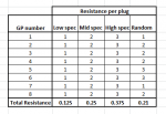
The TM says the spec on the GPs is 1-3 ohms. That means the total resistance of the GPs is between .125 and .375 ohms, with .25 being right in the middle. Given that we have 8 of them, the variations are going to pretty much average out, making that .25 ohm number a pretty safe bet.
Since this is a voltage divider circuit with two resistances (the resistor bank is one, and the total resistance of the GPs is the other) which is designed for a 50/50 (12v/12v) split, we know that the resistances must be equal. So, given the tolerances of the GPs, it makes sense that the resistor bank is the same resistance as the middle of the range for the GP bank, which is .25 ohms. Therefore, the TM is correct, as far as I can see.
I'm back to "30 year old electrical equipment has a high failure rate".
Anyway, problem solved for me. I just took it out. I have no need to be jumped by 24v vehicles, which is the only way the resistor bank offers any benefit.
Since apparently you DO need that benefit, I suggest you take apart the resistor banks, clean them up, and measure the resistance of each individual resistor. I think you'll find that either one has failed in each of them, or there's enough corrosion in there that one is effectively out of the circuit.
I'll see if one of my boys wants to disassemble mine while I'm at work today. Then I can measure each of mine individually.

Last edited by a moderator:


