Wire Fox
Well-known member
- 1,252
- 161
- 63
- Location
- Indianapolis, Indiana
All, this was a question I had asked a while back and a member was kind enough to provide me his instructions he had floating around, but they were limited and suffered from the reprint-of-a-reprint syndrome. While browing some TMs for equipment I probably will never own (GRC-240), I just happened to notice that an offset antenna mount was standard equipment with this kit, plus it had an excellent write-up on how to install this antenna assembly and a list of all parts used. The best part was that it is all in excellent, vector quality from a non-scan PDF. I've gone ahead and extracted all of the pages relating to the offset antenna installation and put them in one PDF for you guys to reference. It starts out with installation instructions and several drawings to show the assembly. It's followed up by the same drawings again (the number labels were slightly different in the two sets of drawings) and closes with a list of parts used in assembly.
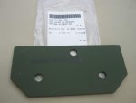
Installation notes: If you have a cargo cover installed, you're going to have to remove the rear-corner tie-down loop, since it will get in the way of the offset antenna (it mounts high). I also don't think we'll ever see the proper spacers and reinforcement plates again, so I'll try and measure out what thickness of spacer will be needed to clear the "top cap" of the rear fender and its rivets. The reinforcement plates aren't quite as critical, as that should just be a slightly oversized, thicker piece of metal that has the same hole pattern drilled through it. This exists purely so that the antenna mount won't tear through the thin aluminum during high wind or a strike against a tree or other object. I personally plan to buy the same thickness and material that's used for the troop seat supports, as that should be more than sufficient to support an antenna.
View attachment Offset Antenna Extract Diagram.pdf


