• Steel Soldiers now has a few new forums, read more about it at: New Munitions Forums!

  • Microsoft MSN, Live, Hotmail, Outlook email users may not be receiving emails. We are working to resolve this issue. Please add support@steelsoldiers.com to your trusted contacts.

Onan mep-017-a troubleshooting

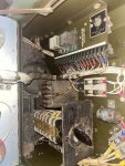
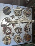
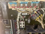
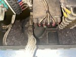
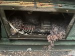
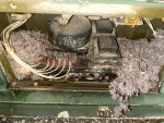
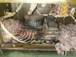
This is going to be a long one. I have a onan mep-017a I just picked up, and doesn’t make power, well it does but it’s only 30 volts at 59 hertz. First thing I should note is the rats got to it, and there’s a lot of work the electrical needs. Engine runes great with only 26 hours. Anyone who has a parts machine and or has experience with this machine, please reach out to me.
 

Guyfang

Moderator
Staff member
Moderator
16,923
24,548
113
Location
Burgkunstadt, Germany
Have you downloaded all the TM's from the TM forum?
The 30 volts you are reading is exciter voltage.
Shoot us some pictures.
The wires need to be fixed before you go any farther.
Did you ever see this gen set run right?
 
Have you downloaded all the TM's from the TM forum?
The 30 volts you are reading is exciter voltage.
Shoot us some pictures.
The wires need to be fixed before you go any farther.
Did you ever see this gen set run right?
exciter voltage? i dont think so.. ill send pics in a bit, but its not a steady 30v, its 30-57 volts at 60 hertz, as far as the wires go, i have replaced all the damaged wires. the main thing i have found is one of the 305 ohm resistors found on the current transformer is shorted, however after removing it, the short remains. im going on a limb here, and replacing the avr as its covered in rat pee and droppings. as far as the engine goes, it runs fine, and apart from a small oil leak from a bad gasket on the valve cover, the engine has no issues. starts via electric start and via pull start, engine makes 50+ psi of oil pressure and sounds correct in the pitch.
and yes i have all the manuals.


one very strange issue i have found is while lines 1,2,3 have continuity to the bus bar, line 0 has no continuity to the bus bar, is this normal?
 

Attachments

exciter voltage? i dont think so.. ill send pics in a bit, but its not a steady 30v, its 30-57 volts at 60 hertz, as far as the wires go, i have replaced all the damaged wires. the main thing i have found is one of the 305 ohm resistors found on the current transformer is shorted, however after removing it, the short remains. im going on a limb here, and replacing the avr as its covered in rat pee and droppings. as far as the engine goes, it runs fine, and apart from a small oil leak from a bad gasket on the valve cover, the engine has no issues. starts via electric start and via pull start, engine makes 50+ psi of oil pressure and sounds correct in the pitch.
and yes i have all the manuals.


one very strange issue i have found is while lines 1,2,3 have continuity to the bus bar, line 0 has no continuity to the bus bar, is this normal?
if say all im seeing is the exciter voltage, what would be the most likely issue? i have replaced the few damaged wires, but with all the corrosion from the pee, most of the electric looks in bad shape. i plan on replacing the capacitors, resistors. i have already cleaned and tested all the rotary switches and what not. i however cant seem to find the exact 305ohm resistor, is there any modern replacements? searching up the part number comes up with nothing.
 
Last edited:

kloppk

Well-known member
Steel Soldiers Supporter
2,169
3,619
113
Location
Pepperell, Massachusetts
I searched and could not find an exact replacement. 305 is an oddball value.
Since those resistors are the burden resistors for the CT's I suspect you could use a 300 ohm 3 W resistor. 300 instead of 305 would only change the circuit by about 1.5%. 300 ohm resistors are plentiful.
 

Guyfang

Moderator
Staff member
Moderator
16,923
24,548
113
Location
Burgkunstadt, Germany
Normally when the AVR went bad on these sets, it was simply, No output at all. But you get 30-57 VAC. When running, will the ACV change slowly? Or quickly peg back and forth? While it is running, can you move the variable resistor back and forth, and have any influence on the ACV?Below is the variable resistor test procedure. simple and quick. Then you can exclude this from the possible problem list.

5. GENERATOR FAILS TO BUILD UP RATED VOLTAGE
Step 1. Check for loose, cut, broken, and worn wiring.
If connections are loose, tighten them. If wiring is damaged, repair it. Refer to paragraph 4-39
for repair instructions.
Step 2. Check for a broken or cracked voltage selector switch.
Check for damaged wiring.
If the voltage selector switch is damaged or defective, refer to paragraph 4-37 for removal and
installation instructions.
Step 3. Inspect the variable resistor for cracks, corrosion, loose connections and other damage. Test the
variable resistor as follows:
a. Stop the generator set and disconnect terminal 26 of the voltage regulator terminal board.
b. With a multimeter, check resistance across the variable resistor terminals by varying the
resistor from full counterclockwise to full clockwise position. This reading should move smoothly
from 0 to 750 ohms ± 10% as the variable resistor is rotated to the full clockwise position.
NOTE
On sets manufactured prior to 1968, this reading will be 0 to 250 ohms ± 10%.
Replace the variable resistor (para 4-16) if the reading is not within specifications.
Step 4. Check the voltage regulator for loose wires, corrosion, metal to metal contact, or incorrect wiring.
6. VOLTMETER READING TOO HIGH OR TOO LOW
Step 1. Check for a broken or cracked voltage adjusting rheostat switch. Inspect for broken wiring or
loose connections around the switch.
If voltage adjusting rheostat switch is damaged or defective, refer to paragraph 4-38 for
removal and installation instructions.
Step 2. Check for broken or cracked voltmeter. Inspect for broken wiring or loose connections. Test
voltmeter by connecting an additional voltmeter to load terminals of generator set and taking
comparative readings to establish validity of generator set voltmeter.
If voltmeter is damaged or defective, refer to paragraph 4-33 for removal and installation
instructions.

In the TM 5-6115-332-14, page 5-2 starts the DS troubleshooting. This is where you are going to find your solution I think. I wont post it here, as its long.


This is also something to check. Often when someone removed the wires, they did not hook the AVR back up as stated on the AVR data plate.
1733915661904.png
 
Normally when the AVR went bad on these sets, it was simply, No output at all. But you get 30-57 VAC. When running, will the ACV change slowly? Or quickly peg back and forth? While it is running, can you move the variable resistor back and forth, and have any influence on the ACV?Below is the variable resistor test procedure. simple and quick. Then you can exclude this from the possible problem list.

5. GENERATOR FAILS TO BUILD UP RATED VOLTAGE
Step 1. Check for loose, cut, broken, and worn wiring.
If connections are loose, tighten them. If wiring is damaged, repair it. Refer to paragraph 4-39
for repair instructions.
Step 2. Check for a broken or cracked voltage selector switch.
Check for damaged wiring.
If the voltage selector switch is damaged or defective, refer to paragraph 4-37 for removal and
installation instructions.
Step 3. Inspect the variable resistor for cracks, corrosion, loose connections and other damage. Test the
variable resistor as follows:
a. Stop the generator set and disconnect terminal 26 of the voltage regulator terminal board.
b. With a multimeter, check resistance across the variable resistor terminals by varying the
resistor from full counterclockwise to full clockwise position. This reading should move smoothly
from 0 to 750 ohms ± 10% as the variable resistor is rotated to the full clockwise position.
NOTE
On sets manufactured prior to 1968, this reading will be 0 to 250 ohms ± 10%.
Replace the variable resistor (para 4-16) if the reading is not within specifications.
Step 4. Check the voltage regulator for loose wires, corrosion, metal to metal contact, or incorrect wiring.
6. VOLTMETER READING TOO HIGH OR TOO LOW
Step 1. Check for a broken or cracked voltage adjusting rheostat switch. Inspect for broken wiring or
loose connections around the switch.
If voltage adjusting rheostat switch is damaged or defective, refer to paragraph 4-38 for
removal and installation instructions.
Step 2. Check for broken or cracked voltmeter. Inspect for broken wiring or loose connections. Test
voltmeter by connecting an additional voltmeter to load terminals of generator set and taking
comparative readings to establish validity of generator set voltmeter.
If voltmeter is damaged or defective, refer to paragraph 4-33 for removal and installation
instructions.

In the TM 5-6115-332-14, page 5-2 starts the DS troubleshooting. This is where you are going to find your solution I think. I wont post it here, as its long.


This is also something to check. Often when someone removed the wires, they did not hook the AVR back up as stated on the AVR data plate.
View attachment 937073
what im seeing is no pattern in the voltage, it doesnt steadily increase or decrease, the voltage is different every time i start the set. ill check the variable resistor, but it seems to be fine as when turning it, the voltage changes a bit.
 

Guyfang

Moderator
Staff member
Moderator
16,923
24,548
113
Location
Burgkunstadt, Germany
That set is older than you. That is the first AVR in it, from the stone age. What is in the TM is the newer version. Its not world famous for reliability, but way better than whats in there now. Up till now, In all the years I worked on Army gen sets, that's only the 2-3 old time, original AVR I have seen. It belongs in a museum. :ROFLMAO:
 
That set is older than you. That is the first AVR in it, from the stone age. What is in the TM is the newer version. Its not world famous for reliability, but way better than whats in there now. Up till now, In all the years I worked on Army gen sets, that's only the 2-3 old time, original AVR I have seen. It belongs in a museum. :ROFLMAO:
Are the new ones just drop in? I got a newer style one from a friend for 20 bucks
 

Guyfang

Moderator
Staff member
Moderator
16,923
24,548
113
Location
Burgkunstadt, Germany
I think so. Its been 50 years since I put one in. But I think so. Make SURE you have the right one. The NSN or part number HAVE to be right.
 

Guyfang

Moderator
Staff member
Moderator
16,923
24,548
113
Location
Burgkunstadt, Germany
I see no mention of any changes. You may have a problem seeing wire numbers, as the control panel is "Dirty" to say the least. The -14 has test procedures for both types.
 

Ray70

Well-known member
Steel Soldiers Supporter
2,634
6,079
113
Location
West greenwich/RI
as the control panel is "Dirty" to say the least.
Understatement of the year, award winner!
Who's car is missing the carpet underlayment?
Someone seems to have put it all inside your generator, then peed on it... :ROFLMAO: :ROFLMAO: :ROFLMAO: :ROFLMAO: :ROFLMAO:
Seriously though.... cleaning up all the rusty connections ( assuming the mouse hotel has been removed ) needs to be first in order.


Top
AdBlock Detected

We get it, advertisements are annoying!

Sure, ad-blocking software does a great job at blocking ads, but it also blocks useful features of our website like our supporting vendors. Their ads help keep Steel Soldiers going. Please consider disabling your ad blockers for the site. Thanks!

I've Disabled AdBlock
No Thanks