Hey Mike, here's your answer courtesy of Jonathon Emery from the list. I'll take the flak from JE about reposting it but I doubt that he will mind.
I'd like to have a little discussion here about M35 lighting with any fellow
electrical types and any one else interested in improving the lighting
system on thier M35, or for that matter most any M series vehicle.
I am going to attempt to make my deuce DOT compliant. I have taken detailed
pictures of an M35-A3 which seem to have almost everything that DOT requires.
This can be broken down to two issues:
1) Wiring the existing front parking lights and rear tail lights to function
as normal vehicles do.
2) Adding the additional required front and rear ID, side clearance, and
backup lights.
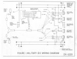
Start with item #1. I have been studying the TM9-2320-361-20 and if you
look at the big foldout schematic near the back, the front parking lights
are circuit 491 which connect to pin "L" of the light switch. This is
only ever on when the panel light lever is in the park position. The rear
tail lights are circuit 21 which connect to pin H of the light switch. These
are only on when the main switch lever is in the service drive position. A
note in the -10 says that to get both front and rear parking lights you must
turn the main light switch lever to the service drive position and the
panel light lever to park. This of course turns off the headlights. So you
cannot ever drive with front parking lights and headlights on a the same time.
Now if you get out a TM9-2320-218-20 for the M151-A2 and look near the
middle for the schematic (page 2-90 and 2-91), you will find that they have
externally (external to the light switch that is) connected circuits 491 and
21 together, look just to the left of the light switch. The net effect of
this is that you will now get both front and rear parking lights when the
panel lever is in the park position, just like the first detent on most
normal civy light switches. And, so long as the panel light lever is in any
position other than park, you will get the front parking lights on when the
tail lights are on along with the headlights when in the service drive
postion. Seems to be exactly what I'd want. By the way, do not try to
figure out the schematic on page 2-100 of the 361-20, it is wrong, look at
the big fold out one in the back.
Any comments?
Now for issue # 2. Whoever did the rebuild job on the M35-A3's did the
following. They installed a plate on the rear of the bed at each corner
that contains a backup light and a ID light. Then they cut a large rectangle
hole out of the rear panel of the bed, including the existing hole for the
trailer plug, and installed the remaining 3 red ID lights (five total on the
back). They also add a smaller plate on the side of the bed at the rear for
a side clearance light, same type as used for the ID lights and red also.
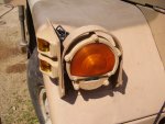
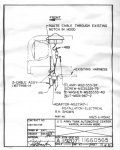
At the front they add a small plate that bolts to the fender and comes
forward and bolts to the guard ring for the front composite light, an amber
clearace light is mounted on the plate facing sideways. This little detail
for the front is actually shown in the 361-20 on page 4-69. Obviously all
these added lights would be wired into the new combined circuit number
491-21. This could all be accomplished by making up little Y adapter cables
so that you would not have to cut the existing harness anywhere. The only
thing missing is the front ID lights. DOT specs call for a series of 3
amber lights to placed as high up on the vehicle as possible in the front
and centered and one on each side, for a total of 5. I don't recall seeing
any of the front ID lights on that M35-A3 and I did not have any pictures
of them. Question is, there is no permanent structure to mount anything on
any higher than the cowl. You could put 3 amber lights say on the upper
windshield frame near the center then put one amber light at each outside
edge of the windshield frame facing forward. Anyone ever given these front
ID lights any thought? The mil-spec light units are pretty big for mounting
in this area. You can get some pretty small light units, they would not be
mil-spec but it would be plenty simple to put 24v bulbs in them and of
course you'd have to run a wire up to the top of the windshield frame.
Then there is the issue of the backup light. In my pictures it appears to
be a catalog item right out of the Peterson book, other than perhaps
changing to 24V bulbs. Not exactly mil-spec but it's also not something
necessary for any tactical situation. As far as powering them, you would
have to add another wire to the harness. I suppose tap off of circuit
461-462 that connects to pin J of the light switch. Run that to a switch
that would tickle the rod that sticks out the back of the tranny. Cole
Hersey has a page or more of that type of switch listed. That way the
backup lights will work when the the main light switch is in the stop or
service drive position only.
Because the truck is short enough you wouild not need any indermediate side
clearance lights.
I think I've covered all the DOT requiements. The only real problem is to
figure out the 5 front ID lights. AND, can the light switch handle all the
added current our would one have to add a relay and run a seperate wire(s)
to all the new added lights? Is there or is there not a circuit breaker
inside the light switch? The M151 book shows one and the M35 book does not.
Anyone else interested in working on this? I am going to make up the
brackets for the rear lights and I'll make the little one for the front
clearance light if I can't find any original ones. Could make many if
others are interested.
I'll be out of town till monday but I'm looking forward to any replies.
later,
je
_____________________________________________________
 I know someone here has to know hte answer....


