• Steel Soldiers now has a few new forums, read more about it at: New Munitions Forums!

  • Microsoft MSN, Live, Hotmail, Outlook email users may not be receiving emails. We are working to resolve this issue. Please add support@steelsoldiers.com to your trusted contacts.

Picked up 6 MEP-802A gensets and will be documenting making them all runners here

pclausen

Well-known member
Steel Soldiers Supporter
452
281
63
Location
Afton, VA
Ok, with my meter in series with the ammeter, my readings are essentially the same as before.

I get basically 0 volts AC across all the burden resistors under load.

Here's the same 4,100 watt load as before with the Fluke 75 across the R10 burden resistor:

IMG_0752.JPG

I get the same 0 volts AC reading across R11 and R12 under the same 4,100 watt load.

Like before, the unit trips out @ 4,100 watts after about 60 seconds. It trips out with the 5,600 watt load after about 10 seconds.
 

kloppk

Well-known member
Steel Soldiers Supporter
2,145
3,526
113
Location
Pepperell, Massachusetts
Can you re-do the current measurement and measure the AC voltage across R11?

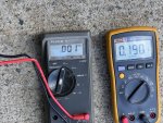
With 0.19 amps AC thru R11 the voltage across the terminals should be 1.42 volts AC.

Here is a diagram of the %Load circuit in 120/240 mode and AMVM set to the 3 o'clock position.

Pct Load.jpg
 

pclausen

Well-known member
Steel Soldiers Supporter
452
281
63
Location
Afton, VA
Thanks for the diagram Kurt! I traced everything through and the path through S8 and the 2 paths through S6 both check fine.

I re-measured the voltage across R11 and I'm getting 0.72 volts AC, give or take. I scraped the solder join a little with my probe and started getting a reading.

So it would appear I'm getting exactly half of what I should be getting. Without unsoldering anything, being in 120/240 mode and AMVM in the 3 o'clock position, the resistance I see across the resistors are as follows:

R101.0 Ohm
R113.5 Ohm
R121.0 Ohm
R137.5 Ohm
R1420 Ohm

I'll unsolder R11 on the left side and re-measure. If that resistor has truly turned into a 3.5 Ohm one, it would make sense my voltage across it is only 50% of what it should be.
 

pclausen

Well-known member
Steel Soldiers Supporter
452
281
63
Location
Afton, VA
That would be awesome!

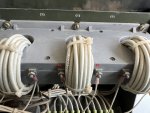
I did unsolder the wire going to the left side of R11. It measures 7.5 Ohm like it should.

These are the B1 and B2 terminals for CT2, right?

IMG_0762.JPG
 

pclausen

Well-known member
Steel Soldiers Supporter
452
281
63
Location
Afton, VA
Yesterday I was pretty beat and didn't even think about measuring the burden resistor values on my other sets, all set to 120/240 mode and AMVM in the 3 o'clock position. Here goes:

802 with issue (I redid the measurements this morning)803802802802
R101.00.80.80.82.1
R112.81.75.57.51.3
R121.00.80.60.80.8
R137.67.60.81.11.0
R1420.420.220.220.220.4

All the sets above have working ammeters that show the expected readings except for the first one. I'm scratching my head a little regarding the readings I'm getting for some of them...

I didn't mention it yesterday, but I swapped the ammeter from the 802 with the issue, with the one in my 803. Both ammeters work like they should in the 803, so I think we can rule out it being the issue.

Here's the 803 under load:

IMG_0759.JPG

@ 12 kW, the ammeter from the 802 with the issue, is reading just shy of 100%:

IMG_0757.JPG

I'm thinking that maybe I should remove S8 and clean all the contacts like I did on the previous unit, since both of them were exposed to the element for a period of time prior to me getting them. I might see if I can do with without removing the switch since that was a real pain on the last one.

Very curious to see what reading you guys get across those burden resistors since mine are all over the place.
 

kloppk

Well-known member
Steel Soldiers Supporter
2,145
3,526
113
Location
Pepperell, Massachusetts
Your readings for R12 & R13 indicate a probable contact problem in S8.
With S8 set to 120/240 R13 gets hooked in parallel to R12. So when checking the resistance across R12 & R13 you should get virtually the same resistance. Since you aren't and R13 is reading 7.6 ohms this would cause K8 to think there is an overload problem when there actually isn't.
R12 & R13 is parallel would yield an equivalent burden resistor of 3.75 ohms. With poor contact in S8 connecting R13 in parallel to R12 would yield a higher resistance. This higher resistance will cause a higher voltage to develop across the pair of resistors. This higher voltage is sensed by K8 and is interpreted as an overload condition.

Diagram for that...
Pct Load 2.jpg

Resistance readings on my 802 are:
R10 0.9 ohms
R11 2.6 ohms
R12 0.9 ohms
R13 1.2 ohms

R14 20.2 ohms R14 isn't a burden resistor. It's used in the field flashing function.


The %Load meter is only driven by CT2/R11 and does not display currents sensed by CT1 & CT3.
This is why your %Load meter can display less that 100% load but still get an overload fault when K8 senses an "overload" from CT1/R10 or CT3/R12/R13.
 
Last edited:

pclausen

Well-known member
Steel Soldiers Supporter
452
281
63
Location
Afton, VA
Kurt, I think you hit the nail on the head (again)!

I cleaned the contacts on S8 13/14 and here are my before and after readings:

ResistorBeforeAfter
R100.81.0
R111.75.0
R120.80.8
R137.61.7

Before cleaning S8 13/14, I see seeing about 10 Ohms across the contacts and 0 Ohms after.

I'll fire the set back up around lunch time and see what I get.

If things are still not correct, I'll go ahead and clean all the contacts on S8, even though it will be a pain, but I think I can get to most of them by removing the leads going to them, one pair at a time. The very back ones will be challenging, but hopefully I won't have to do those.
 
Last edited:

pclausen

Well-known member
Steel Soldiers Supporter
452
281
63
Location
Afton, VA
Fired the unit up and ran it for a few minutes @ 2.26 kW to warm it up. I then brought it up to a 4.1 kW load for break-in run #2 (~80%).

These are the voltage readings I got:

Resistor2.26 kW4.10 kW
R100.66 V1.36 V
R110.49 V1.34 V
R122.80 V4.96 V
R131.50 V1.83 / 1.20 V

A note on that 1.83/1.20 V reading. The initial reading was about 5 minutes into the run. The 2nd reading was after 40 minutes. Maybe a sign that I still have some contacts to clean on S8?

The ammeter still did not register. I did not have my meter connected in series during this run to double check the figures. I wanted to let the 1 hour run @80% complete. Later this afternoon once it has fully cooled down, I'll do another run, this time taking it up to 100% load. I'll be sure to have my meter connected for that run.

The good news is that it no longer shuts down with an 80% load.

I'm still concerned I might have done something to the engine during that initial run @40% where it shut down from overheating since the thermostat was stuck closed. Still kicking myself for not feeling the hoses for proper flow and putting that 40% load on it before verifying same. And of course doing the run in the first place without a functioning coolant temp and oil pressure gauge. But that is water under the bridge at this point I suppose.

This is the 1st start of the day after sitting overnight. No pre-heat since ambient was around 55F:


This video is about 20 minutes into the 80% load run:


From most angles there is no discernable smoke, except a hint of grey smoke when the camera is pointed into the garage.

Here's another short clip at around the 30 minute mark looking into the garage, which is about the only angle you can see the smoke.


And lastly, another short clip showing the vibration of the engine as evidenced by the oil cap chain:


You can't really tell due to the low frame rate, but the whole engine is vibrating. Hopefully I'm just paranoid from the overheating incident Saturday, but this set doesn't seem to run quite as smooth as my other ones. I guess I'll reserve judgment until I complete the 3rd and final break-in run at 100%. If it will hold a 100% or 120% load a few minutes, I suppose everything is ok.
 
Last edited:

Daybreak

2 Star Admiral
Steel Soldiers Supporter
1,522
771
113
Location
Va
Howdy,
It sounds silly, but, you know the MEP's are PF 0.80
12kw load showing 100% is correct for using purely resistive loads

Hopefully your using a break in oil. Or a straight non-detergent oil.
 

Guyfang

Moderator
Staff member
Moderator
16,766
24,072
113
Location
Burgkunstadt, Germany
I said I was not going to get involved again if you continued to work on all these gen sets in one thread. And this is the last post I will make here. You were wrong to run the set with two safety systems disconnected. Even more wrong is the fact that you are running it at high and max loads, without the box on it. The box channels the air flow and helps keep the engine and main gen cool. How is it supposed to properly cool the engine if the air flow is more or less, not flowing through the radiator? How is the main gen supposed to keep cool if the air is not being forced through it. Your not even supposed to run it with the doors open.
 

pclausen

Well-known member
Steel Soldiers Supporter
452
281
63
Location
Afton, VA
@Daybreak Yep, PF 0.80 and I agree that 12kw load is 100% That pic from from my 803 with the ammeter from my 802. I'm running the JD Break-In Plus oil that I believe you recommended in another thread.

@Guyfang Sorry for continuing posting to this thread. Now that all the sets are running and making power, I'll create separate threads for the final tweaks each set require to get them to 100%. Also get your point about not doing load tests without the covers in place. From what I can tell, the fan shrouds at the radiator forces all the air the fan is pushing through it, but you are correct that without all the covers in place, the air does not get pulled through the main gen. I did keep an eye on gen temp during the 80% test and it never went above 110F. I'll hold off on doing the final load test until the covers are in place, but I don't want to put the covers on until the last electrical gremlins are sorted out. I'm also going to re-torque the head bolts after that over heat incident.

I might come back and post a final summary here once they are all 100%, just to provide a conclusion to this long running thread. Really appreciate all the help along the way from everyone!
 

pclausen

Well-known member
Steel Soldiers Supporter
452
281
63
Location
Afton, VA
Figured I'll bring a proper closure to this thread.

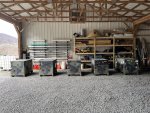
I sold one 802 already, so it unfortunately won't be featured in this piece. But I do have 4 units running and making power along with a 803 cousin.

Here they are:

IMG_0816.JPG

Starting them up and shutting them down, one at a time:


All 5 of them running next to each other:


Thought that would be a proper closure to this thread.

I do love me some 803. That guy wakes up in an instant compared to a 802. I guess 2 extra cylinders will do that. Also has a lot more room inside the cabinet to work on the engine, AND it has foam insulation for quiet operation which the 802s don't have. At least none of the 6 units that passed though my hands did.
 
Top