• Steel Soldiers now has a few new forums, read more about it at: New Munitions Forums!

  • Microsoft MSN, Live, Hotmail, Outlook email users may not be receiving emails. We are working to resolve this issue. Please add support@steelsoldiers.com to your trusted contacts.

Preventive maintenance, now big sparks at rear battery.

edpdx

Active member
794
75
28
Location
Oregon
I've been dealing with what seemed to be a parasitic draw for the past 3 weeks. Some mornings the battery is dead. Some mornings it fires up strong. After charging the newish interstate front battery, I decided to look at the Alternators this morning and test them. I tested with multi-meter set to DIODE. One probe to alt case and one to BAT lead. Results: Driver side Alt .035/.035. Passenger side Alt 1.189/.334 (Driver side ground lead tried at case and ground lead as well).

Not certain, but Drivers side Alt seems bad if I understand the test? Having said that. I buttoned up the Alts and was planning a trip to the Alt rebuilder shop. BUT... When I reconnected the battery Starting with POS REAR (OK), NEG REAR $*!# SPARKS!- the big ones, not "Oh, I left my phone charger plugged into the lighter" kind.

Aside from cleaning the leads on the passenger side alt, I didn't do anything else to attribute the fireworks too- aside from the battery (front) running down intermittently, the M1009 has been starting and running fine.

What can I check that may be responsible for the sudden sparking- I dare not "Just connect it".
 

edpdx

Active member
794
75
28
Location
Oregon
Something to consider, maybe. Yes? No?

I found this snippet from a review I just read on Amazon. I dawned on me that I tightened the BAT Nut on the Alt perhaps a little too tight so I went looking to see if that was even a known thing- smashing through the fiber isolating washer and shorting the power to the case?

"Item was used. Painted black inside but could still see the rust. It also shorted because they screwed the bolts in too tight and went through the plastic washers that caused it to ground out. Not a new item they lied."
 

edpdx

Active member
794
75
28
Location
Oregon
The negative of the rear battery is the positive of the front battery. I think you are correct that the isolated ground lug of ALT 1 is no longer isolated.
Thanks, Barrman. Just to be clear, I started by connecting the rear POS, got sparks touching the cable to rear NEG. Stopped. No cables attached to FRONT BATTERY.
Just so I can understand the mechanism- what points to your conclusion?

Is a new Drivers side ALT the solution? Is the
isolated ground lug a replaceable part?
 

Barrman

Well-known member
5,253
1,760
113
Location
Giddings, Texas
The CUCV is wired so the rear battery negative is connected to the positive of the front battery. If you look at the terminal the big wire goes to the front battery and the small red wire goes over to the diamond shaped Buss bar next to the glow plug relay. that is the 12 volt positive supply for the truck.

With the front battery negative connected. Sparks when putting that terminal on to me said ALT 1 issue. However, I missed the part about the front battery negative not hooked up at the time. So, now my thinking goes to ALT 2 not being isolated since ALT 1 has nothing to spark about. Sorry for the confusion.
 

Keith_J

Well-known member
3,657
1,319
113
Location
Schertz TX
Something to consider, maybe. Yes? No?

I found this snippet from a review I just read on Amazon. I dawned on me that I tightened the BAT Nut on the Alt perhaps a little too tight so I went looking to see if that was even a known thing- smashing through the fiber isolating washer and shorting the power to the case?

"Item was used. Painted black inside but could still see the rust. It also shorted because they screwed the bolts in too tight and went through the plastic washers that caused it to ground out. Not a new item they lied."
The passenger side alternator could have damaged isolators on either positive or negative connections. See this video, test between the positive and negative terminals..
 

edpdx

Active member
794
75
28
Location
Oregon
The passenger side alternator could have damaged isolators on either positive or negative connections. See this video, test between the positive and negative terminals..
Keith, After watching the video attached, I went back to recheck the alternators. In continuity setting on the MM, I got NO continuity on either alternator. I removed all the wires, as shown in the video, and holding one lead to the case and the other to the NEG got no continuity , switched the leads and same. Then applied the same test to the POS terminal and case, and no continuity . Went and repeated the test on the passenger side and no continuity either way. The test shown are to determine if the diode is shot, So either this test does not apply yo Isolated ground alternators, OR something is shot in BOTH ALTS?
 

edpdx

Active member
794
75
28
Location
Oregon
Found this buried in a 12 year old post: ALTERNATOR TESTS Original post July 17, 2010

To test that an alternator is an Isolated ground alternator, place a lead from your ohm meter on the case(outside housing) of the alternator and place the other lead on the ground stud. If there is NO continuity, then you either have an isolated ground alternator, or a BAD alternator. To be 100% sure, you would need to look inside it and test every internal item and know what you are looking for to see that it is not grounded by the case. -Doghead 7/18/2017

So, since I find no continuity on either ALT that should mean that both are isolated, and possibly bad as well. Is this a simple test at an alt shop, or will I be better off $wise to just get new alts?

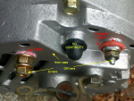
P.S. The Suppressor attached to the bracket in the photo is no more, shoul I track one down and install it?

1666831318148.png
 

Keith_J

Well-known member
3,657
1,319
113
Location
Schertz TX
Keith, After watching the video attached, I went back to recheck the alternators. In continuity setting on the MM, I got NO continuity on either alternator. I removed all the wires, as shown in the video, and holding one lead to the case and the other to the NEG got no continuity , switched the leads and same. Then applied the same test to the POS terminal and case, and no continuity . Went and repeated the test on the passenger side and no continuity either way. The test shown are to determine if the diode is shot, So either this test does not apply yo Isolated ground alternators, OR something is shot in BOTH ALTS?
You need to test again, this time using only the negative and positive terminals on each alternator. These are the terminals on the back, the positive is in the recessed portion and should have a red isolator.

The drivers side will have a black 6 gauge wire from negative terminal to one of the intake manifold studs. The positive connects to the 6 gauge red wire.

Passenger alternator has the negative terminal connected to a 6 gauge red wire with white stripe. The positive terminal is connected to a solid red wire, also 6 gauge.
 

edpdx

Active member
794
75
28
Location
Oregon
You need to test again, this time using only the negative and positive terminals on each alternator. These are the terminals on the back, the positive is in the recessed portion and should have a red isolator.

The drivers side will have a black 6 gauge wire from negative terminal to one of the intake manifold studs. The positive connects to the 6 gauge red wire.

Passenger alternator has the negative terminal connected to a 6 gauge red wire with white stripe. The positive terminal is connected to a solid red wire, also 6 gauge.
Keith, a little clarification, please: "this time using only the negative and positive terminals on each alternator". AM I still checking for continuity? If so between what 2 points? -the POS and NEG terminals
 

Keith_J

Well-known member
3,657
1,319
113
Location
Schertz TX
Keith, a little clarification, please: "this time using only the negative and positive terminals on each alternator". AM I still checking for continuity? If so between what 2 points? -the POS and NEG terminals
Use diode test on the digital multimeter. Test the positive and negative terminals forwards and back per the video I posted.

You have eliminated any isolator fault.

Do not worry about the external capacitor, it is only for radio frequency interference suppression.
 

Keith_J

Well-known member
3,657
1,319
113
Location
Schertz TX
Keith, a little clarification, please: "this time using only the negative and positive terminals on each alternator". AM I still checking for continuity? If so between what 2 points? -the POS and NEG terminals
Continuity will work just fine. Test black lead of multimeter to negative, red to red. Then the other way.
 

edpdx

Active member
794
75
28
Location
Oregon
Keith, SOOOO with Multi-Meter on CONTINUITY mode I get:
DRIVER ALT: RED lead to B-, BLACK lead on B+ 1.0
DRIVER ALT: RED lead to B+, BLACK lead on B- 1.099
PASS ALT: BLACK lead to B-, RED lead on B+ 1.0
PASS ALT: BLACK lead to B+, RED lead on B- 1.132

Tested for continuity:
REAR BATT NEG to PASS ALT NEG wire CONNECTOR: Has Continuity.
REAR BATT POS to PASS ALT POS wire CONNECTOR: NO Continuity_____BUT it does show continuity to the grounded engine. What does that mean? * NOTE: As of these tests only the POS cable is attached to the REAR Battery. Front Battery is not connected.
 
Last edited:

edpdx

Active member
794
75
28
Location
Oregon
So in my search for a parasitic draw or outright short I ended up with a big spark when attaching the rear battery. I could not continue the search for the short until I figured why I was getting such a huge spark. Read for days, cleaned leads, even replaced the GP solenoid. Out of ideas I decided to trace wires to figure it out. All battery cables disconnected: Attached rear POS= OK so far. Attached rear NEG >SPA*RK< I missed this when I posted Red Item in Post #13 above. Looking at the red wires that go to the passenger ALT, I see they both look the same- did I mix them up? Tested for continuity for the BIG RED wire I was attaching to the B- Terminal and found it WAS continuous to the POS lead of the rear BATTERY. DOH! I screwed them up because I used the presence of the rubber boot only on the B- Lead. My mind just assumed that it must be the POS lead. 3 DAYS %#*! Got it all back together and started up like a summer day. Hate to admit a lame oversight, but I like to leave posts resolved. Thanks to all that helped.

Now I just have to track the parasitic draw.
 

edpdx

Active member
794
75
28
Location
Oregon
In the interest of resolving the initial problem, I offer my humility. During the tracing of the apparent faulty circuit, I found that the piggybacked fuse holder I installed to by-pass the burnt-up headlight fuse holder in the block had an unseated fuse- one leg was partially out. All had been fine previously, no I'm uncertain how this condition came about, but I'm relieved I've discovered it. Thanks for all input.
 
Top
AdBlock Detected

We get it, advertisements are annoying!

Sure, ad-blocking software does a great job at blocking ads, but it also blocks useful features of our website like our supporting vendors. Their ads help keep Steel Soldiers going. Please consider disabling your ad blockers for the site. Thanks!

I've Disabled AdBlock
No Thanks