• Steel Soldiers now has a few new forums, read more about it at: New Munitions Forums!

  • Microsoft MSN, Live, Hotmail, Outlook email users may not be receiving emails. We are working to resolve this issue. Please add support@steelsoldiers.com to your trusted contacts.

PTO rebuild issues

Jeepjake

Member
69
1
8
Location
Bend, OR
Just in case you need bearings, I just ordered a complete bearing set from Mark Boyce at Boyce Equipment. Great service there and reasonable pricing, he had every bearing for the pto and the pto rear output aux drive. The only parts he couldn't run down were the thrust bearings for the output shaft, but I had to make special ones anyway.
Make darn sure you get the thrust bushing lock tabs properly placed on the output shaft to prevent them from spinning.

Whoever rebuilt my pto last didn't and it ground .112 inch off the case and required a modified thrust bearing to be made to move everythign back where it belonged.

Cheers!
Jeep
 

Jeepjake

Member
69
1
8
Location
Bend, OR
Hey, speakin of PTO output flanges... Anyone out there have an extra kickin around they would like to sell to a guy :)

PM me if ya do, it is the missing puzzle piece for my pto install...well that and a pto lever bracket...

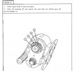
oh, JCKnife a helpful hint if you think your bearings and thrust bushings are still good, be cautious when removing the output shaft, after removing the cross pin that fixes the gear to teh output shaft, the TM says to tap the shaft and the rear bearing out (cupped needle bearing) but it fails to alert you to align the shaft keyway (in the middle of the shaft, you cant see it from the end) with one of the four scallops on the thrust bushing, not doing so will destroy the thrust bushing on the way out.
To do this easily, go ahead and tap far enough to get the closed end needle bearing out of the way, then before driving the shaft the rest of the way out, look down the shaft with a flashlight from the end that the cupped bearing was installed, when you rotate the shaft you should be able to see where the keway is cut in the output gear, make sure that keyway is visible through one of the "scalops" in the ID of the thrust bushing and the shaft should tap the rest of the way out no prob.
The rest of the pto is pretty darn easy, and all goes swimmingly by just following the TM.

-Jeep


cheers all
 

JCKnife

Well-known member
1,367
46
48
Location
Kentucky
Great info, thanks everyone. I've already got those cage bearings out and they appear to be in good shape. That was the part I was most worried about after reading Dave's thread about them. I will go at it again tonight or tomorrow!
 

gringeltaube

Staff Member
Super Moderator
Moderator
Steel Soldiers Supporter
6,987
2,523
113
Location
Montevideo/Uruguay
Last edited:

JCKnife

Well-known member
1,367
46
48
Location
Kentucky
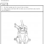
Turns out an 8-hour soak-in of PB blaster was all it needed. That stuff is miraculous. The puller removed the flange with minimal effort (this after trying cheater bar and a propane torch last night--wow).

Onward!
 

JCKnife

Well-known member
1,367
46
48
Location
Kentucky
OK, if I contribute nothing else new to this process, I can offer this: in the step described herein, instead of using a brass punch, I found that a 1-1/8" socket used in an arbor press is an ideal way to remove this oil seal.
 

Attachments

davey8943

Member
334
2
18
Location
Columbus IN
JCKnife: I would not recommend hitting that flange with a hammer! Material is soft and relatively thin (little over 1/4") and may end up deformed.
Get a stronger puller if the first one was to small or weak. And while under tension do a quick heating of the hub, with a wet rag wrapped around the shaft.

...

G,

Now that you say something, I may have pulled the flange with a puller and PB Blaster. The PTO is now mounted on the truck, but I don't see any impact marks on the flange.

I think I was remembering beating the snot out of the woodruff key that was between the flange and the shaft (after removing the flange). I ended up completely destroying the key getting it out.

Thanks for keeping me from giving JC some potentially destructive advice!
Dave
 

JCKnife

Well-known member
1,367
46
48
Location
Kentucky
OK I got the little crack in the housing welded up and I'm ready to start re-assembling this thing.

One thing I wish I had done differently: I removed the oil seals when I tore it down and it's been a couple months. I'm not sure which way they were turned. Is there a rule-of-thumb to follow when pressing the new seals in?

Also on the surfaces that have gaskets: use just the gasket or also Permatex? Permatex on one side of the gasket or both?

Thanks.
 

clinto

Moderator, wonderful human being & practicing Deuc
Staff member
Administrator
Super Moderator
Steel Soldiers Supporter
Supporting Vendor
12,596
1,132
113
Location
Athens, Ga.
One thing I wish I had done differently: I removed the oil seals when I tore it down and it's been a couple months. I'm not sure which way they were turned. Is there a rule-of-thumb to follow when pressing the new seals in?

Also on the surfaces that have gaskets: use just the gasket or also Permatex? Permatex on one side of the gasket or both?

Thanks.
I don't know how to describe it, but the lip of the seal face the direction of the liquid you are trying to keep from escaping. Perhaps someone here can describe it better than I can. I know how to install a seal looking at it, but not a clear way to describe it.
 

m16ty

Moderator
Moderator
Steel Soldiers Supporter
9,580
218
63
Location
Dickson,TN
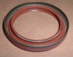
The spring goes on the inside is another way to describe which way the seals go. Look at the pic. The side facing up goes toward the oil. The side facing down goes toward the outside.
 

Attachments

clinto

Moderator, wonderful human being & practicing Deuc
Staff member
Administrator
Super Moderator
Steel Soldiers Supporter
Supporting Vendor
12,596
1,132
113
Location
Athens, Ga.

JCKnife

Well-known member
1,367
46
48
Location
Kentucky
Thank you I understand on the open-style seals but still wondering about the closed ones. I do have a couple in my winch bodies I think. I'll look at those over the weekend but any further description appreciated.
 

JCKnife

Well-known member
1,367
46
48
Location
Kentucky
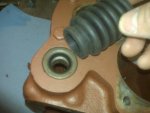
OK next issue: the TM says that after this seal is in, then press in the boot. Does the lip of the boot go all the way through and inside the seal? I don't see any other way, but then with the boot inside the seal, the shaft really isn't against the seal at all--it's against the boot. Is there room for both? Any advice here appreciated.
 

Attachments

gringeltaube

Staff Member
Super Moderator
Moderator
Steel Soldiers Supporter
6,987
2,523
113
Location
Montevideo/Uruguay
OK next issue: the TM says ......
No, it doesn't....:)

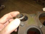
After the seal is in - not flush in this case but all the way down to the bottom of the hole - you have about 5.5mm left for the metal cup (pic) It goes pressed in just like the seal and comes to sit flush to the housing surface.
Then - install the boot's lip (with some lube) and then comes the shaft.

G.
 

Attachments

JCKnife

Well-known member
1,367
46
48
Location
Kentucky
Oh dear. So there's a metal cup that holds the boot in? I don't think I saved those. In fact I don't remember seeing them...I did take the old seals out but that's the only piece I recall taking out of those holes. I think both boots were gone off this PTO when I started.
 

gringeltaube

Staff Member
Super Moderator
Moderator
Steel Soldiers Supporter
6,987
2,523
113
Location
Montevideo/Uruguay
Yes; and no big deal, those parts can easily be made (turned with lathe), if you can't find them online or elsewhere.
Let me know if you need dimensions.

G.
 

JCKnife

Well-known member
1,367
46
48
Location
Kentucky
Yes; and no big deal, those parts can easily be made (turned with lathe), if you can't find them online or elsewhere.
Let me know if you need dimensions.

G.
I fired an e-mail to George at White Owl to see if he has them. If anyone has other ideas let me know. G, is there an "official name" for those cups?
 

gringeltaube

Staff Member
Super Moderator
Moderator
Steel Soldiers Supporter
6,987
2,523
113
Location
Montevideo/Uruguay
Official like from the TM......???:)

TM9-2520-246-34P, fig.12; item 14 shows:
Part# 7376534, CUP RETAINING: TO ATTACH SHIFTER SHAFT BOOT


G.
 
Top
AdBlock Detected

We get it, advertisements are annoying!

Sure, ad-blocking software does a great job at blocking ads, but it also blocks useful features of our website like our supporting vendors. Their ads help keep Steel Soldiers going. Please consider disabling your ad blockers for the site. Thanks!

I've Disabled AdBlock
No Thanks