• Steel Soldiers now has a few new forums, read more about it at: New Munitions Forums!

  • Microsoft MSN, Live, Hotmail, Outlook email users may not be receiving emails. We are working to resolve this issue. Please add support@steelsoldiers.com to your trusted contacts.

Questions regarding M123 brakes........

FIREFIGHTER

New member
20
1
3
Location
Sandown,NH
Hey guys...........long time listener, first time caller!!

My Fire Dept has an M123A1C that was converted to a forestry tanker. I've taken over as maintenance officer, chief wrench turner a few years ago and noticed that the thing didn't stop for crap. The brakes were WAY out of adjustment, a couple of the shoes were fractured. All those issues have since been corrected, but the thing still stops like crap. Since it only goes out a few times a year it really wasn't a priority for them to fix.

I have removed the air lines for the service brakes and done pressure tests. The Front brake lines are getting 50 PSI and the REAR brakes are getting 55 PSI as measured at the air lines disconnected from the cans themselves. According to the Organizational Maintenance Manual TM 9-2320-206-20. 2-175 Brake Application Valve.............connect an accurate pressure gauge in the service line at the rear of the vehicle and open the service cock. The pressure at the rear of the vehicle and open the service line cock. Is the service line the air line going to the service port in the air can?? B.) Depress the Treadle valve to the floorboard. The test gauge should register the same as the pressure gauge on the dash. Assuming the pressure gauge on the dash is accurate, the pressure readings should be the same.

I also read that the differential brake lever on the side of the steering column will only put out 55 PSI so I'm wondering if at some point during the years MAYBE someone connected an air line in the wrong position somewhere underneath. I haven't found any diagrams showing how the air lines are supposed to routed.

So where is the service line at the rear of the vehicle??
I believe I am supposed to be getting 85-105 PSI +/- to brake cans both front and rear. Whatever the air compressor is putting out for pressure. Am I wrong in that assumption??
Might the rods going from the brake pedal to the treadle valve be out of adjustment and not allowing the treadle valve to depress all the way??

Starting to get frustrated.............any help would be appreciated, Thank you!!
 
Last edited:

topo

Well-known member
909
256
63
Location
farmington NM
I would check the travel on your brake chambers from all the way in (foot off the pedal ) to all the way out (foot on the pedal ) If it uses type 30 chambers 2 inches of travel is the legal max .
 

NDT

Well-known member
Steel Soldiers Supporter
10,436
6,486
113
Location
Camp Wood/LC, TX
The chambers should see full line pressure with the brake pedal pressed hard. The service line at the rear of the vehicle is the glad hand near the pintle hitch marked "service". It receives the same pressure as the chambers. 55 psi is less than half of maximum brake application, no wonder the truck has weak stopping power. I would start by checking on the travel of the brake actuation valve, might be severely out of adjustment.
 

FIREFIGHTER

New member
20
1
3
Location
Sandown,NH
Thanks NDT........that was what I was going to try on Monday. And thank you for clarifying what the service line was for me, I wasn't quite sure so that's why I pulled the line right off the can. That way I know exactly what I'm getting at the can for pressure. No guessing!!

And thank you Topo for the reply, the slacks are adjusted so the stroke on the cans is between 1" - 1 1/4"
 

NDT

Well-known member
Steel Soldiers Supporter
10,436
6,486
113
Location
Camp Wood/LC, TX
Sure FIREFIGHTER, my 123 is fresh out of fire service, so if I can assist with pictures or "mine is like this" observations, I will be happy to help. Thanks for taking the initiative, you might save someone's life.
 

FIREFIGHTER

New member
20
1
3
Location
Sandown,NH
Thank you............now if I can get the rest of the guys to see what I see, then the battle would be won. The responses of "....It's always been like that, what's the problem??!!", ".........the truck only goes out on a few calls a year, why the big deal?? " ('cause when you've got 30k of truck, loaded w/ 25k lbs of water, plus 2-3k lbs of steel tank on top....that adds up to a crapload of weight and I know if I'm driving something...........I WANT IT TO STOP!!!)..............AND MY FAVORITE COMMENT....."Your just looking for problems, aren't ya??!!"

I won't drive the truck. I don't want to be the one responsible should some soccer mom (or dad) w/ load of kids whose talking on the cell phone or texting not see the truck coming and pull out in front and not be able to stop............or some kid who runs out in the road..........or fill in the blank. However, I'm not allowed to take it out of service because THEY don't see the problem since it has always been like this. And so, on I march; trying to resolve what I see is a problem.

Thanks for listening to the rant........I'll get off my soapbox now and go back to looking at the manuals.
 

NDT

Well-known member
Steel Soldiers Supporter
10,436
6,486
113
Location
Camp Wood/LC, TX
That truck is designed to stop a 40,000 lb trailer loaded with a 100,000 lb tank from 40 mph. It should be able to lock up all 10 wheels with ease. Good luck.
 

FIREFIGHTER

New member
20
1
3
Location
Sandown,NH
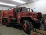
PIC of our Forestry Tanker (BIGFOOT) while doing tank repair last year

P3280692.jpg

I have some better photos on the computer at the station. I thought I had some on my laptop, but I can't find them. I will post what I find out about the brakes after I figure out what is going on with them. Anyone know where or how much a new valve would be?? NSN 2530-00-304-9424
I have done a search online (many searches) but haven't found one listed. Broke down and filled out my info and requested a quote from Part Target and others who came up after doing an NSN search.
 

FIREFIGHTER

New member
20
1
3
Location
Sandown,NH
No, the M123A1C that has been converted to our Forestry tanker is it. We only have a few guys who are qualified to drive it........I should say that I will let drive it. Straight cut gears on the tranny and it seems the latest generation of firefighters has been brought up on Auto Tranny's. That and all our other trucks have auto tranny's as well.
Bear Brook State park (The Forestry Depot) has another M123A1C that another town had converted to a Forestry Tanker as well. Unfortunately, that town extended the tank well aft of the rear drive axle and it was prone to doing WHEELIES going up a grade or popping the clutch!!! :) Bear Brook also has 2 complete diesel engines that have been sitting OUTSIDE exposed to the rain and snow for years. No shipping containers, just some duct tape that has rotted off over the years. That was very sad to see when I went up looking for parts.

QUESTION: Has anyone modified the air delivery valve for the foot brake with any other treadle valve/ air delivery valve from anything else (on highway truck/ current production military vehicle)?? I'm not having any luck finding a replacement valve.
Has anyone removed the air delivery valve and rebuilt it??
Love the truck and the copious amounts of water it can deliver into the woods, but this is starting to get ridiculous finding parts and the money the parts are costing.
 

FIREFIGHTER

New member
20
1
3
Location
Sandown,NH
Results of investigation for lack of braking power

So this morning I pulled the SERVICE BRAKE AIR SUPPLY line off of the quick release valve and had a competent person MASH DA BRAKES with 100 PSI of air in the tanks. I had an external air line off of the station compressor charging the tanks to 100 PSI. The brake peddle hit the floorboard at full depression and delivered 75 PSI. This indicated the brake peddle linkage was out of adjustment. However, upon crawling in, out, under, and around the truck; it was very apparent that access to almost all of the clevis adjustments would be a HUGE BEAR to get to. I was able to access the clevis right at the service brake valve via the hinged access panel in the floorboard just in front of the drivers seat. I screwed the clevis all the way in, thusly raising the height and increasing the travel of the brake pedal. Now full tank pressure can be applied while the brake pedal is an 1" or 1 1/2" above the floorboard. In other words, the pedal doesn't hit the floorboard while being applied and you don't end up doing a ballerina toe point trying to get full application of the brakes. I took the truck out for a test drive and found that braking performance was better, but still not the way I wanted it to be.

Now at some point in this trucks life.......maybe 10 years ago, or so I'm told......the truck had a tractor protection valve added and the rears cans were changed out for 30/30 spring brake and service brake cans (smart thinking, especially on a single circuit vehicle). HOWEVER, the supply lines running off the double check valves are only 3/8" air brake tubing. You measure tubing by the OD of the tubing, for those that don't know this. The ID of the 3/8" air brake tubing is only 1/4" (0.251"). The inlet into the can has a 3/8 NPT threaded port and this is reduced down to 1/4" NPT to accept the 3/8" air brake tube fitting.

So........I'm getting the pressure now, but the 3/8" tubing is restricting the volume of air required to fill the chambers; thusly increasing the time and stopping distance of the truck. Like filling a 5 gallon bucket with a 1/4" garden hose and then filling the bucket with a 1/2" hose. More water is going to flow out of the 1/2" hose.

I think what I am going to do is swap out the 3/8" air brake tubing for 1/2" tubing. The ID of the 1/2" tubing is about 3/8" (0.375) if I remember correctly. However, I think that the stock quick release valve lines going to the double check valves are 1/4" copper tubing.

And then toward the end of the afternoons adventures, I found that the right front air can (which is stock OEM military) has a small rust hole on the top that is venting. Wasn't there this morning!! And then I found some electrical issues with the emergency lights, a problem w/ 2 way radio (seems to want to transmit all the time after its been on for a few minutes)!! And then I packed up my tools and went home...............Guess the truck figured I needed more to do!! aua
 

FIREFIGHTER

New member
20
1
3
Location
Sandown,NH
Neglected to mention that after the adjustment of the clevis at the delivery valve and the road test, I removed the service air line at a rear can and re-measured the air pressure just to make sure I didn't have a PRESSURE restriction at the quick dump or double check valve. Pressure was still 100 PSI.

TOPO.......what size cans would you put on?? Braking force seems to adequate with the 30/30's, it's just the braking time w/ the small lines that seems to be the issue. If you look at the braking systems on 'modern' tractors or trucks, they utilize 1/2" hose w/ 3/8" NPT fittings going into the cans. And they use 30/30 cans. Not trying to be disrespectful, just trying to learn and educate myself further. And thank you for your suggestion.
 

topo

Well-known member
909
256
63
Location
farmington NM
I hope some one with a 10 ton would help with this . I said 30/30 chambers may be to small because that is a common size for trucks running 11 24.5 tires and your running duel 14-24 tires . I drove a Mack and Internationals with 12-24 tires and they had larger air chambers then 30/30 .
 

FIREFIGHTER

New member
20
1
3
Location
Sandown,NH
Replacement Brake chamber and there size for an M123A1C

So after Topo brought up the thought that maybe the 30/30 brake chambers might be to small, it starting my own doubts as well. The next size up brake cans would be the 36/36's for the princely sum of about $150/each. And then the question of whether they would fit or not also entered my mind. QUESTIONS, QUESTIONS, QUESTIONS............

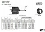
So I did some research on the original equipment and came up w/ a Bendix number. And just to be on the safe side, I put a call into Mack; since they are the ones who built the truck. Mack got back to me this afternoon and confirmed that, indeed; the original brake chamber was a 30 sq. inch brake chamber. Bendix part number 229819. I tried inserting the jpeg of the Bendix literature that Mack sent to me, but it only show up like a postage stamp. Not much use, but I'll leave it in just in case you can blow it up and read it some how.

Rotochambers.jpg

http://www.bendixvrc.com/itemDisplay.asp?documentID=2395

What is interesting is that the inlet ports on the original Roto Chambers were only 1/4". It states that on the postage stamp JPEG I uploaded above. It is also interesting that they made Rotochambers 36 and 50 Sq inches. Wife giving me the evil eye.......spending too much time on computer. But this is what I have discovered.
 
Last edited:
Top
AdBlock Detected

We get it, advertisements are annoying!

Sure, ad-blocking software does a great job at blocking ads, but it also blocks useful features of our website like our supporting vendors. Their ads help keep Steel Soldiers going. Please consider disabling your ad blockers for the site. Thanks!

I've Disabled AdBlock
No Thanks