sewerzuk
Member
- 524
- 12
- 18
- Location
- Seaside, OR
So…most of us with 3 phase MEP generator sets have wondered if it is possible to rewire the set for something other than 120/208 or 240/417v. Some have asked the question in the forum here and the consensus seems to be that it won’t work. I think it will.
*I am using one of my MEP-004a’s for testing, so the numbers I am posting are related to its power/current/voltage ratings.
Why re-configure? Well, many of the people who own these generators use them only in single phase, at 120/208v. According to the TM, this is permissible, and the vast majority of 240v appliances operate just fine at 208v. But…there are a few loads that don’t like 208v. And, you are limited to 100% of rated current for each phase; so unless you are sending power to 2 separate services, you can only get about 43A, or 9kW. Re-configuring the set for its intended use nets you more useable power, and provides more appropriate voltage for the loads.
I began thinking about the possibility of re-configuring my MEP-004a the other day, and spent a few hours reading through Steelsoldiers and Smokstak; although there were a few stories of a guy who knew a guy whose buddy’s brother-in-law rewired an MEP for single phase, I couldn’t find a single post by somebody who had actually attempted it. I went a step further, and wondered if it would be possible to wire the generator in a 3 phase delta configuration, thinking that 120/240 delta would be useful for the small shop with several large 240v 3 phase loads, and a requirement for a light single phase 120v load. So, I spent another few hours poring over the schematics. Here are the conclusions I come up with:
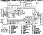
The MEP’s use a standard 12 lead generator head. That means that, from the generator’s point of view, pretty much any standard voltage is possible. The problem is in the generators instrumentation and control system…the current transformers for the ammeter and safety trips are designed around a 3 phase wye setup. There is no provision for single phase in how the CT’s are wired. However…this doesn’t mean that single phase isn’t possible, it just means that there might be a few “quirks” to deal with when running single phase. I think that all of the safety trips will still function properly, as they are all designed around current passing through the individual windings of the generator. It doesn’t matter how the load is placed on those windings…the cumulative current is what is important and that will not change. The wattmeter should work properly. I believe that the voltmeter will also work properly; it will indicate line voltage as designed and simply read 0 when switched to the phase not being used (for single phase). The ammeter should also indicate current…however it may be a little confusing. It may indicate actual line current, ½ line current, or 1/√3 line current depending on how the switch is selected and the method I choose to re-wire the generator. This is because of where the CT measures the current (it may be possible to re-wind the CT to work properly, but I’ll jump that hurdle if my re-wire actually works and produces useable power). The voltage regulator should also work properly; it is designed to provide 120v per winding and that is all that is needed to produce the voltages that I am aiming for. 480v 3 phase delta is not possible with this generator, as it requires 240v per winding. I believe the following configurations are possible:
3 phase:
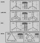
1. 417/240v wye (adjustable from 348/200v up to 480/277v) This is a factory-installed voltage
2. 208/120v wye (adjustable from 173/110v up to 240/138v) This is a factory-installed voltage
3. 240/120v Delta (adjustable from 200/100v up to 277/138v) This does change how current flows through the CT’s and may cause problems with the overload trip and ammeter reading
4. 120v Delta (adjustable from 100v to 138v) I don’t think this is a very useful configuration…don’t know of too many 120v 3 phase loads. But, it should be possible. Same CT issues as 240/120v delta.
Single Phase (both 120/240v configurations produce the same power, just different methods of wiring):
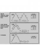
1. 120/240v Double Delta (adjustable from 100/200v up to 138/277v) Same issues with the CT
2. 120/240v low zigzag, or dogleg (adjustable from 100/200v up to 138/277v) Same issues with the CT
3. 240/480v high zigzag (adjustable from 200/400v up to 277/554v) Don’t know how many single phase 480v loads are out there, but 554v might be useful for the guy trying to get a little more lightning length out of his Tesla coil. Same issues with the CT
There are a few issues to deal with and things to think about:
1. The cable size going to the main circuit breaker and to the load terminals is too small for the increased current that is possible during single phase operation. It should be upsized appropriately.
2. I believe that no additional current would be traveling through individual generator windings, meaning that you could get the full rated 15kW out of the generator at 120/240v single phase without exceeding the design limits of the windings (however, the overload trip will still limit you to the current ratings from 3 phase operation).
3. The CT 1-3 could be re-wound to indicate proper current on each “leg”. This would also affect the overload trip.
4. Re-winding the CT’s might indicate proper current; however the overload trip is still set to 130% of the 3 phase rated current; meaning that it will still trip at roughly 55A, even though 63A would be the 100% rated current for single phase 120/240. It may be possible to add a properly sized resistor inline with the overload trip relays, as they only have a very small amount of current passing through them. This resistor could be sized to adjust the overload trip to the new 130% rated current of 82A. Another option would be to increase the size of resistors R23, R24, and R25 in the tactical relay box. It also may be possible to remove one turn of the generator leads from the CT; this would change how the ammeter and wattmeter read, and it would also raise the overload trip setpoint by roughly 25% (this is the method I intend to experiment with).
5. L0 is internally bonded to ground in the generator; therefore it would be absolutely critical to remove this bond prior to starting up the generator in delta configuration. Failure to do so would result in a hardwired phase to ground short.
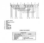
6. T10, T11, and T12 are bonded together under the voltage reconnection board. It is critical to remove/modify this bonding bar for any configuration other than Wye. Failure to remove it would result is a phase to phase to phase short.
7. The generator reconfiguration should be able to be completed all on the voltage reconnection board; a few jumper wires and buss bars would complete the reconfiguration. I’m hoping to come up with a VERY simple reconnection for zigzag; the other connections will require a bit more work. For that reason I’ll try the zigzag first, and if it works I may proceed to experiment with the delta configurations.
I am planning on attempting this in the coming few weeks with one of my -004a sets. Of course I’ll take all of the safety precautions; and I am prepared for the possibility that I may destroy some critical internal components with my meddling (although I don’t think this will happen…otherwise I wouldn’t be trying it).
I’ll set up the video camera when I first fire this thing up, just in case I manage to create molten copper and smoke instead of single phase power.
I think I have a grasp on the problems, pitfalls, etc. associated with this reconfiguration (albeit a loose grasp). I’m looking for input before I try this out…anything I’ve missed? Am I re-creating something that somebody else has already accomplished?
Attached some relevant schematics and diagrams...
edit 1: low zigzag re-configuration is complete; it works mostly as predicted. Details and a video on page 3
edit 2: additional reconnections have been made to correct issues with the installed voltmeter and voltage regulator. Details on page 4
edit 3: I plan to post the entire reconnection process here in this original post once all of the testing is complete
edit 4: here is the completed process:
http://www.youtube.com/watch?v=YmF4Awr3uc4
Attachments
-
80.9 KB Views: 335
-
61.9 KB Views: 322
-
102.6 KB Views: 312
-
68 KB Views: 296
-
54.3 KB Views: 277
Last edited:


